AsProgrammer dregmod
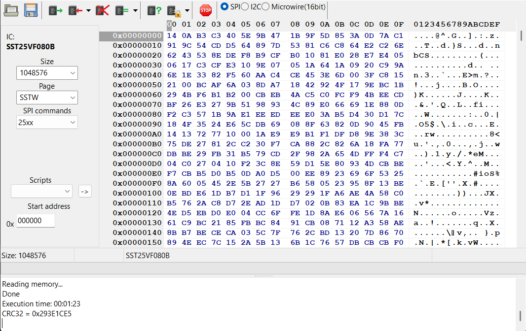
AsProgrammer dregmod is a free and open source Windows program that reads, writes, erases and verifies SPI flash and I2C EEPROM chips. It’s a fork of AsProgrammer with support for the Bus Pirate, which it drives through the BPIO2 binmode.
In this demo we’ll read an SST25VF080B SPI flash and an AT24C256 I2C EEPROM with a Bus Pirate 6.
Connections
SPI flash
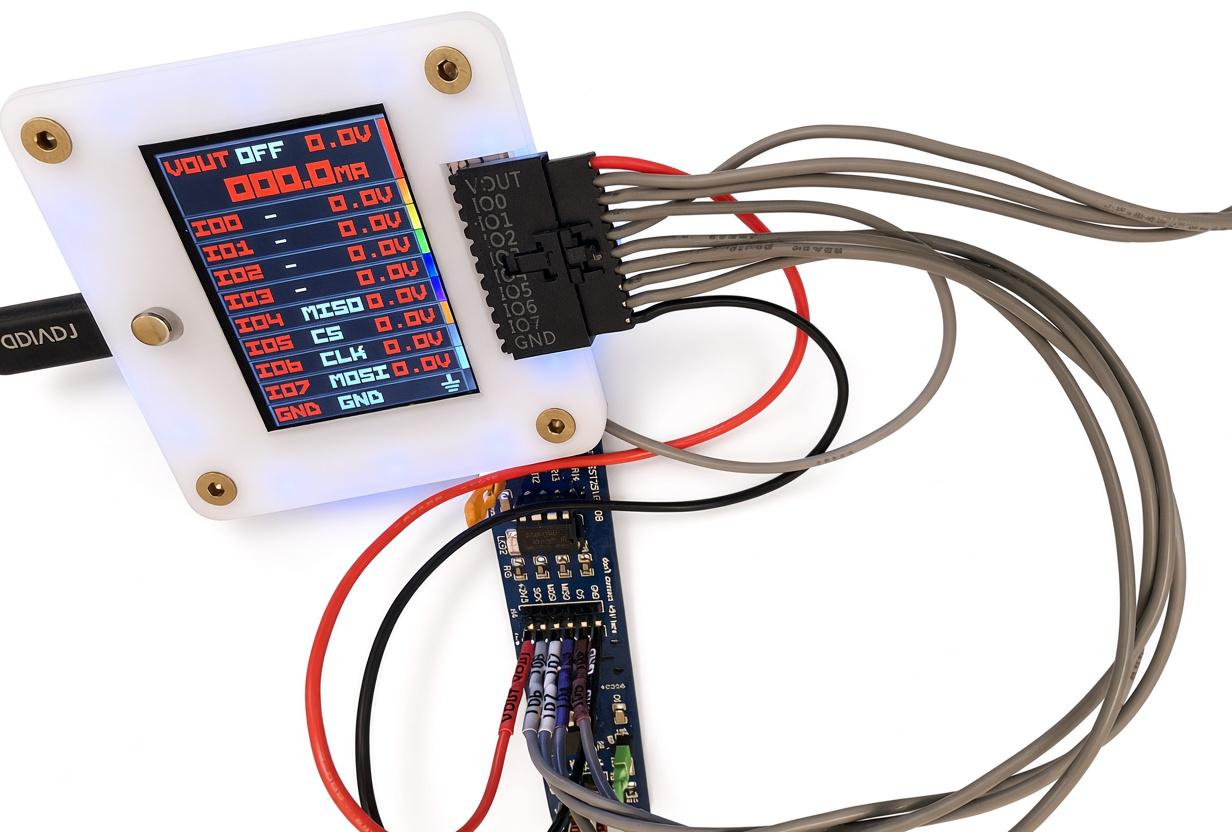
| Bus Pirate | SST25VF080B board | Description |
|---|---|---|
| VOUT | +3V3 | Power supply (3.3 volts) |
| IO4 | MISO | Master In Slave Out |
| IO5 | CS | Chip Select |
| IO6 | SCK | Clock |
| IO7 | MOSI | Master Out Slave In |
| GND | GND | Ground |
On a bare chip, tie WP and HOLD to VCC: AsProgrammer doesn’t drive them.
I2C EEPROM
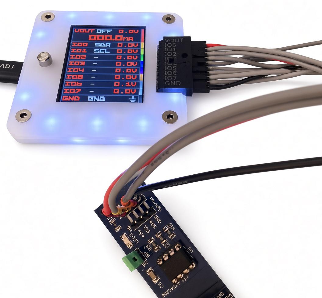
| Bus Pirate | AT24C256 board | Description |
|---|---|---|
| VOUT | +5v | Power supply |
| IO0 | SDA | Data |
| IO1 | SCL | Clock |
| GND | GND | Ground |
I2C needs pull-up resistors on SDA and SCL. This board has them, so the Bus Pirate pull-up resistors stay off.
Bus Pirate setup
Update the Bus Pirate to the latest firmware first.
HiZ> binmode

 1. SUMP logic analyzer
 2. BPIO2 flatbuffer interface
 3. Arduino CH32V003 SWIO
 4. Follow along logic analyzer
 5. Legacy Binary Mode for Flashrom and AVRdude
 6. IRMAN IR decoder (LIRC, etc)
 7. AIR capture (AnalysIR, etc)
 8. Bus Pirate v3 unbrick: bootloader v4.6 (ICSP)
Select binary mode
x to exit (1) >
In the Bus Pirate terminal use the binmode command and choose BPIO2 flatbuffer interface. Answer y to Save setting? and the Bus Pirate keeps BPIO2 after a restart. To check, type i: the Active binmode line shows BPIO2 flatbuffer interface. PulseView, Flashrom and AVRDUDE use other binmodes: select theirs again with binmode when you go back to them.
AsProgrammer setup
Open the Hardware menu and choose BusPirateV5+.
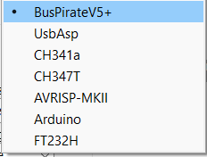
In the BusPirateV5+ menu, open COM port and choose the port marked BPIO2. The other port of the pair is the terminal. If the ports have no labels, see find the binmode port.

In the same menu, set Voltage to the voltage of your chip.
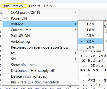
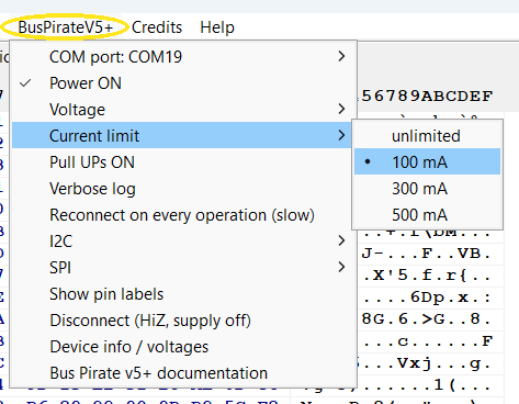
Set Current limit. The power supply turns off if the chip draws more. 100mA is a good value for a flash or EEPROM chip.
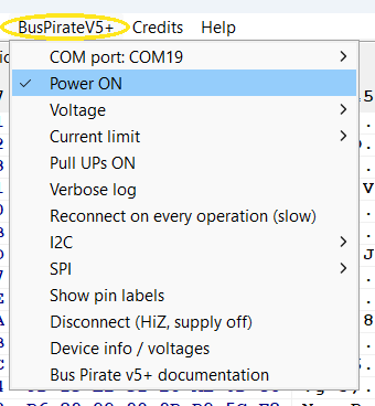
Leave Power ON checked, so the Bus Pirate powers the chip from VOUT. Check Pull UPs ON only for an I2C chip on a board without pull-up resistors.
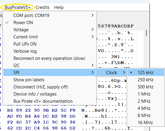
Set the SPI clock in SPI, Clock. Start at 125kHz and raise it once two reads give the same CRC32.
Set the I2C clock in I2C, Clock. Start at 50kHz.
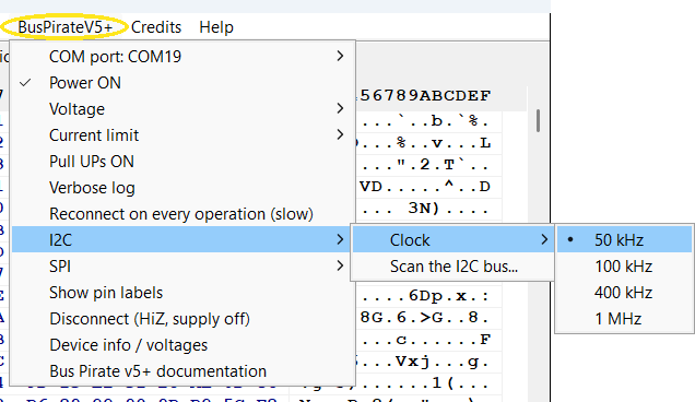
Three more commands in the same menu:
Show pin labels labels the pins of the bus you picked, SPI or I2C, on the Bus Pirate’s screen, so you can see where each wire goes. It turns off the power supply and the pull-up resistors while you wire, and the next operation sets them again as the menu says.
Device info / voltages shows the Bus Pirate model, its firmware, and the power supply settings and measurements. It doesn’t turn the power supply on, so it’s a safe first check.
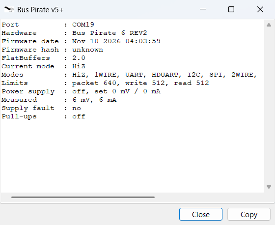
Disconnect (HiZ, supply off) turns off the power supply and the pull-up resistors, puts the pins in HiZ and closes the COM port. Use it before you unplug the chip or open the port with another program. If the log says the target may still be powered, unplug the Bus Pirate.
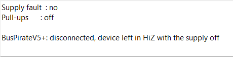
AsProgrammer keeps the settings of the last session, voltage included. With Power ON checked, it turns on the power supply at the first operation on the chip, for example Read ID or Scan the I2C bus…, and leaves it on until you choose Disconnect (HiZ, supply off) or close AsProgrammer. Wire the chip and check the voltage first: 3.3 volts can destroy a 1.8 volt chip.
The toolbar

The toolbar buttons have no labels: hold the pointer over one to see its name.
| # | Button | What it does |
|---|---|---|
| 1 | Open file | Loads a file into the hex editor |
| 2 | Save file | Saves the hex editor to a file |
| 3 | Read IC | Reads the chip into the hex editor |
| 4 | Program IC | Writes the hex editor to the chip |
| 5 | Erase IC | Erases the chip |
| 6 | Verify IC | Compares the chip with the hex editor |
| 7 | Read ID | Reads the ID of an SPI flash and lists the chips that match |
| 8 | Unprotect | Clears the write protection bits of an SPI flash |
| 9 | Cancel | Stops the operation that is running |
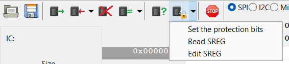
Buttons 4, 6 and 8 have a small arrow on their right. Click the arrow, not the button, for more commands:
Program IC: its menu has one command. It asks once, then runs Unprotect, Erase IC, Program IC and Verify IC in a row. It stops if you click Cancel or the erase ends with an error. If an I2C EEPROM refuses only some pages, it goes on and programs the pages the chip takes.

Verify IC: Blank check checks that the chip is erased.

Unprotect: Set the protection bits writes the status register at once, without asking. Read SREG shows the status registers in the log, and Edit SREG opens an editor for them.
Read an SPI flash
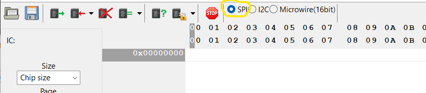
Choose SPI with the radio buttons. Do it before you choose the chip: changing the bus clears the chip size and page size.
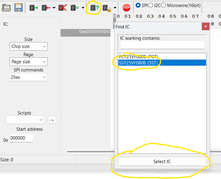
Click Read ID. The Find IC window lists the chips with that ID. Choose yours and click Select IC. If the window doesn’t open, the log shows the ID with (Unknown). FFFFFF or 000000 means the chip didn’t answer: check the wiring and the voltage. Any other ID is a chip that isn’t in the list: see the user guide to add it.
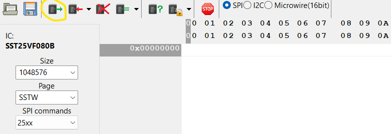
Click Read IC.
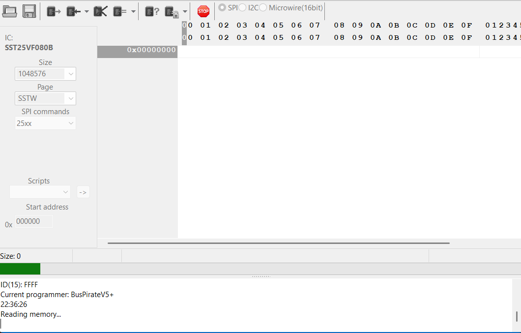
The progress bar at the bottom moves while AsProgrammer reads the chip.
When the log says Done, click Save file to keep the dump. Reading only fills the hex editor.
The log also shows a CRC32 of what was read. Read the chip again and compare: the same CRC32 twice means both reads returned the same data. If the two reads differ, use shorter wires, and go back to a lower SPI clock if you raised it.
Read an I2C EEPROM
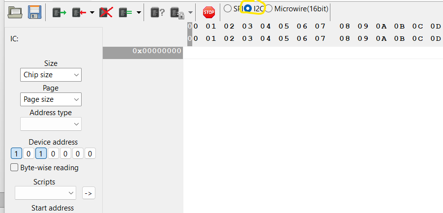
Choose I2C with the radio buttons. Device address holds the 7-bit address of the chip: 1010000 (0x50) for a 24 series EEPROM with A0, A1 and A2 tied to ground.
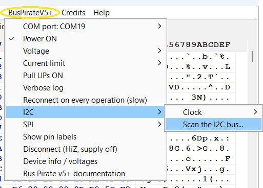
Open BusPirateV5+, I2C, Scan the I2C bus… to check the address.
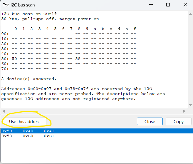
The scan lists the addresses that answer: 0x50 is the AT24C256. Select its row and click Use this address to copy it to Device address.
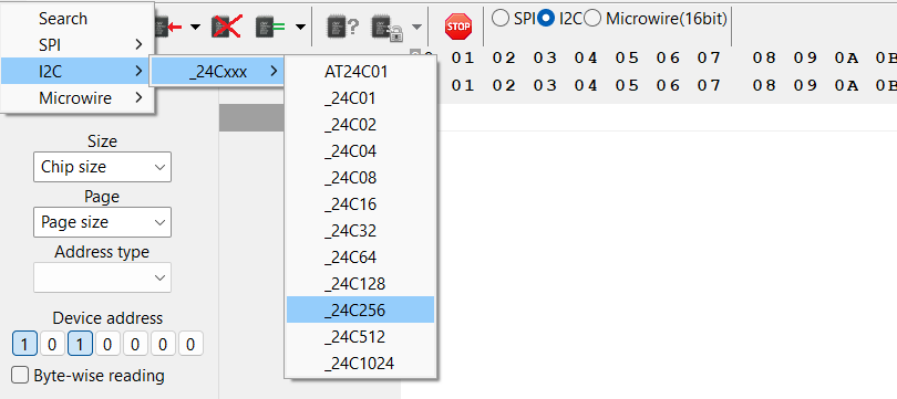
An I2C EEPROM has no ID to read. Open the IC menu, the first in the menu bar, and choose I2C, _24Cxxx, _24C256. AsProgrammer fills in the size, the page size and the address type from its chip list.
Click Read IC. When the log says Done, click Save file.
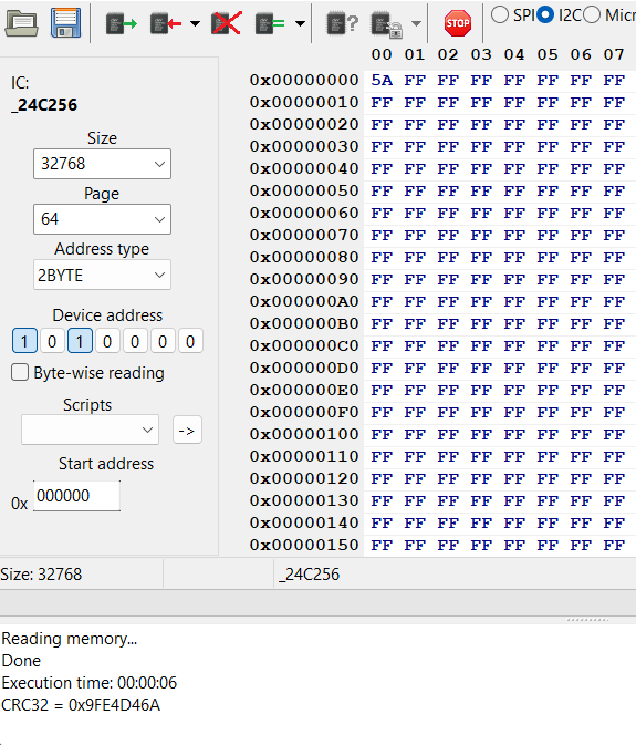
If the log says IC not responding, check the pull-up resistors and the wiring: SDA on IO0, SCL on IO1.
Write a chip
Read the chip and save the file before you write anything: it’s your backup.
Click Open file and choose the file to write. Program IC writes what the hex editor holds.

On an SPI flash click Erase IC, because Program IC doesn’t erase the chip first. If the chip is write protected, click Unprotect before you erase: SST chips like the SST25VF080B power up that way. An I2C EEPROM needs no erase.

Click Program IC, then Verify IC.

The command under the arrow of Program IC does steps 2 and 3 in one go, after one question.
An I2C EEPROM ignores writes while its WP pin is high: tie WP to ground.
Troubleshooting
AsProgrammer can’t reach the Bus Pirate
- Check that BPIO2 is the binmode, see Bus Pirate setup.
- Choose the BPIO2 port, not the terminal port.
- Only one program at a time can open the binmode port. Close anything else using it.
The Bus Pirate stops answering. Unplug it and plug it back in, then close AsProgrammer and open it again. A big chip at a low clock takes a while to read: the 1MB SST25VF080B took 1 minute 23 seconds in this demo.
For more detail in the log, check Verbose log in the BusPirateV5+ menu. Report problems on the AsProgrammer dregmod issues page.