DDR4 RAM SPD I2C Adapter
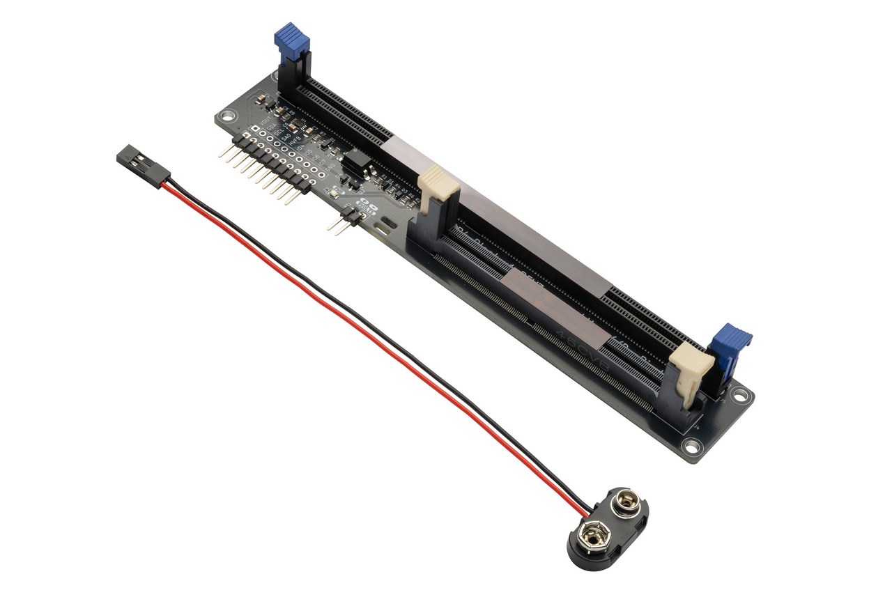
The DDR4 adapter plank makes it easy to read and write the SPD configuration chip on DDR4 UDIMM and SODIMM computer memory modules.
Use the Bus Pirate ddr4 command to read and write the SPD EEPROM on a DDR4 module, or follow the DDR4 device demo to learn about the technical details.
DDR4 adapter plank features:
- 288 pin DDR4 UDIMM socket for standard desktop memory modules
- 260 pin DDR4 SODIMM socket for laptop memory modules
- Accepts a single 5 volt power supply
- A 3.3 volt regulator powers the RAM and I2C level shifter
- A level shifter ensures the I2C pins SDA and SCL are never more than 3.3 volts
- SA0 pin 9 volt high programming voltage is opto-isolated from the Bus Pirate
- SA1 and SA2 are pulled to ground to set I2C address 0x50
- A 9 volt programming voltage is required to lock and unlock the SPD EEPROM write protection. This must be supplied externally by a 9 volt battery (connector included) or bench power supply.
A 9 volt supply is required to write to the SPD EEPROM on a DDR4 module. This voltage is not supplied by the Bus Pirate, so you will need to provide it separately using a 9 volt battery (connector included) or bench power supply. Battery connector provided. Battery and bench supply not included.
Get Bus Pirate & Accessories
Adapter Pinout
| DDR4 adapter plank | Description |
|---|---|
| VOUT | 5 volt power supply for the DDR4 adapter |
| SDA | Level translated I2C Data |
| SCL | Level translated I2C Clock |
| SA0 | Opto-isolated control of 9 volt High Voltage Programming pin (SA0) |
| HVFB | Zener-protected feedback pin to measure 9 volt programming voltage |
| GND | Common ground for the DDR5 module and the Bus Pirate |
When inserting a DDR4 module into the adapter plank, hold the bottom of the PCB with both hands and press the module firmly into the socket. The retaining clips should click into place.
High Voltage Programming
In order to change the write protection bits in the SPD EEPROM, the SA0 pin on the DDR4 module needs to be driven to 9 volts. The adapter includes an opto-isolator to control this pin, but you will need to provide a separate 9 volt power supply (battery or bench supply) to use it. This pin is connected to ground when not used for high voltage programming.
If you don’t intend to change the write protection bits, you do not need to connect a 9 volt supply to the adapter.
| Pin | Description |
|---|---|
| 9VOLTS + | Connect to the positive terminal of a 9 volt battery or bench power supply |
| 9VOLTS - | Connect to the ground terminal of a 9 volt battery or bench power supply |
A 9 volt battery connector is included with the adapter, but the battery itself is not included. You can also use a bench power supply if you have one available.
Why not use a simple SMPS to generate the 9 volt programming voltage? An SMPS has a clock, and would need to be FCC certified. This adds a lot of extra cost to a board that is for previous generation RAM. a 9 volt battery is a simple and readily available alternative.
If this adapter sells well enough to justify the extra cost, we will make a second revision with an onboard 9 volt boost converter. I don’t think it will reach that volume.
SODIMM and UDIMM Connections
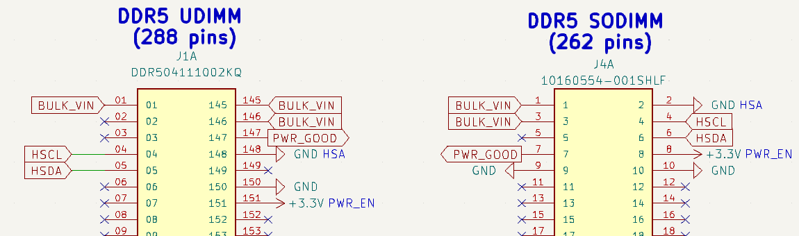
| DDR4 UDIMM (288 pins) | DDR4 SODIMM (260 pins) | Description |
|---|---|---|
| SDA (285) | SDA (254) | I2C Data (3.3volt) |
| SCL (141) | SCL (253) | I2C Clock (3.3volt) |
| SA0 (139) | SA0 (256) | High Voltage Programming pin (+9 volt to change write protection bits) |
| SA1 (140) | SA1 (160) | Address pin 1, ground |
| SA2 (238) | SA2 (166) | Address pin 2, ground |
| +3.3V (284) | +3.3V (255) | 3.3 volt SPD EEPROM supply |
| GND (2) | GND(1) | Ground |
We only need to connect a few pins to access the SPD EEPROM on a DDR4 module. The rest of the pins are used for power, data, and control signals.
- SDA and SCL are the I2C data and clock pins. The I2C pins must be no more than 3.3 volts, the adapter includes a power supply and level shifter to ensure this.
- SA0 is the high voltage programming pin. To change the write protection bits in the SPD EEPROM, this pin needs to be driven to 9 volts. The adapter includes an opto-isolator to control this pin, but you will need to provide a separate 9 volt power supply (battery or bench supply) to use it. This pin is connected to ground when not used for high voltage programming.
- SA1 and SA2 are address pins that set the I2C address of the SPD EEPROM. By connecting these pins to ground we set the address to 0x50.
- +3.3V is the power supply for the SPD EEPROM. This is generated by a voltage regulator from the Bus Pirate VOUT voltage, ensuring the RAM is never powered above a safe level.
- GND is the common ground for the DDR4 module and the Bus Pirate.
There are multiple GND pins on a DDR4 module, but only one needs to be connected to access the SPD hub.
Warning and Disclaimer
Use the DDR4 adapter at your own risk. Don’t experiment with expensive high capacity, high speed, overclocker-special DDR4. We picked up cheap 8GB sticks from an e-Waste recycler, and we don’t care if they get damaged.
THE SOFTWARE, HARDWARE, AND TUTORIAL ARE PROVIDED “AS IS”, WITHOUT WARRANTY OF ANY KIND, EXPRESS OR IMPLIED, INCLUDING BUT NOT LIMITED TO THE WARRANTIES OF MERCHANTABILITY, FITNESS FOR A PARTICULAR PURPOSE AND NONINFRINGEMENT. IN NO EVENT SHALL THE AUTHORS OR COPYRIGHT HOLDERS BE LIABLE FOR ANY CLAIM, DAMAGES OR OTHER LIABILITY, WHETHER IN AN ACTION OF CONTRACT, TORT OR OTHERWISE, ARISING FROM, OUT OF OR IN CONNECTION WITH THE SOFTWARE, HARDWARE, AND TUTORIAL OR THE USE OR OTHER DEALINGS IN THE SOFTWARE, HARDWARE, AND TUTORIAL.
Resources
Get a Bus Pirate
Get Bus Pirate & Accessories
- Browse Complete Bus Pirate hardware collection
- Bus Pirate 5 REV10 with enclosure
- Probe Cable Kit
- Auxiliary Cable Kit
- Quick Connect Adapter
Community
Documentation
Here’s some other fun stuff you might enjoy.