PulseView (Follow Along)
FALA is a “live action” logic analyzer mode that automatically captures everything that happens when you send commands from the Bus Pirate. It eliminates the need to setup triggers and arm a second tool for debugging. We like to call it FALA for short.
- PulseView with FALA mode (Windows)
- libsigrok with FALA mode (Linux experimental)
- Support topic (Windows/Linux)
Currently pre-build FALA support is only available in a special patched version of PulseView for Windows.
Linux users have reported to build libsigrok library that works with FALA and recent versions of PulseView.
All Bus Pirate hardware supports follow along logic analyzer, however only Bus Pirate 6 has a second buffer to capture pins directly. In earlier hardware all output pins are measured behind the IO buffer. This means the logic capture may not match the actual output of the IO buffer. This is not a problem when the Bus Pirate is used as a logic analyzer only and all pins are inputs.
Capabilities
- 62.5MSPS (or more if overclocked)
- 131K samples
- 8 channels
- Trigger: single pin, high or low
- Follow along logic analyzer mode
- Base pin can be set to an internal pin for debugging the Bus Pirate itself
Enable FALA Interface
HiZ> binmode

Select binary mode
 1. SUMP logic analyzer
 2. Binmode test framework
 3. Arduino CH32V003 SWIO
 4. Follow along logic analyzer
 x. Exit
 > 4
Binmode selected: Follow along logic analyzer

HiZ>
Enable the FALA binary interface with the binmode command. This will configure the logic analyzer and send capture notifications to the Bus Pirate’s second serial port.
- Type
binmodein the terminal - Select “Follow along lgic analyzer”
Configure PulseView
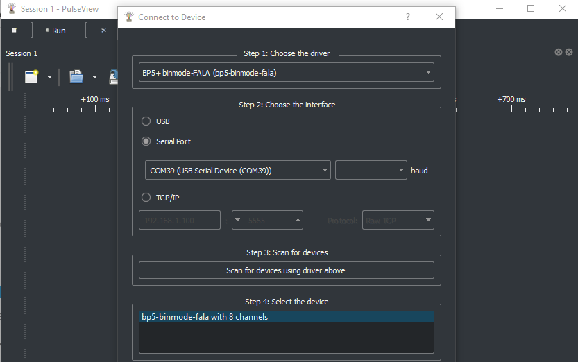
Click “connect to device” and configure PulseView for the Bus Pirate FALA mode.
- Select the
BP5 + binmode-FALAdriver - Select
serial portand choose the Bus Pirate serial port that is not used for the terminal (lower number for me these days) - Click
Scan for devices - Hopefully the Bus Pirate is detected. Click OK.
Run Capture on PulseView
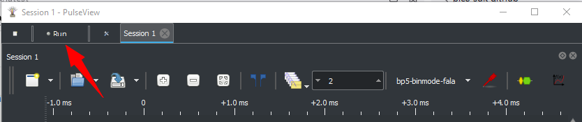
Click “run” to start capturing.
Capture Samples
HiZ> m

Mode selection
 1. HiZ
...
 6. SPI
...
 x. Exit
Mode > 6

Use previous settings?
 SPI speed: 10 kHz
 Data bits: 8
 Clock polarity: Idle LOW
 Clock phase: LEADING edge
 Chip select: Active LOW (/CS)

y/n, x to exit (Y) > y
Enter a Bus Pirate mode. For now, SPI is best for testing.
mto enter a mode, I suggest SPI
Auto Capture Speed
Actual speed: 10kHz
Logic analyzer speed: 80000Hz (8x oversampling)
Use the 'logic' command to change capture settings

Mode: SPI
SPI>
When changing protocol modes with the m command, FALA will automatically set the capture speed to oversample the bus speed by a factor of 8.
Write Data
SPI> W 5
5.00V requested, closest value: 5.00V
Current limit:Disabled

Power supply:Enabled
Vreg output: 5.0V, Vref/Vout pin: 5.0V, Current: 3.2mA

SPI> [0x00 0xff 0x55 0xaa]

CS Enabled
TX: 0x00 0xFF 0x55 0xAA
CS Disabled

Logic analyzer: 288 samples captured
SPI>
Every time you send data to the bus, the logic analyzer will capture samples. Enable the power supply and write some data.
W 5to enable a 5volt power supply[0x00 0xff 0x55 0xaa]write some data to the busLogic analyzer: 288 samples capturedindicates how many samples were captured by the logic analyzer
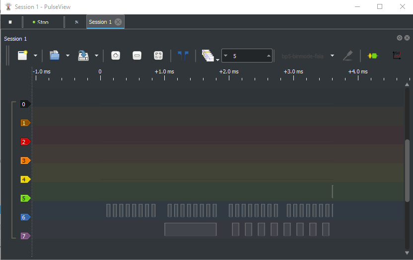
Live Logic View!
The samples are loaded into PulseView every time something happens on the bus.
- You may need to zoom a lot if there are only a few samples
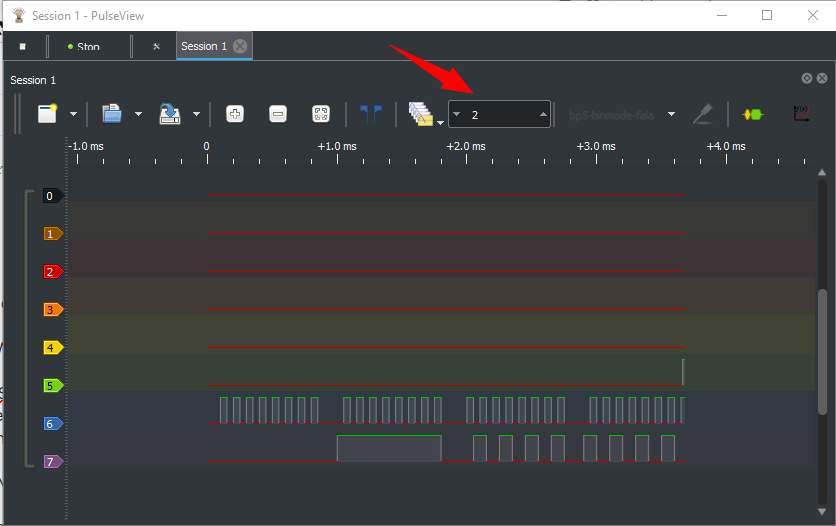
- The box with a 2 (red arrow) indicates the number of captures. Up and down arrows scroll through the capture history
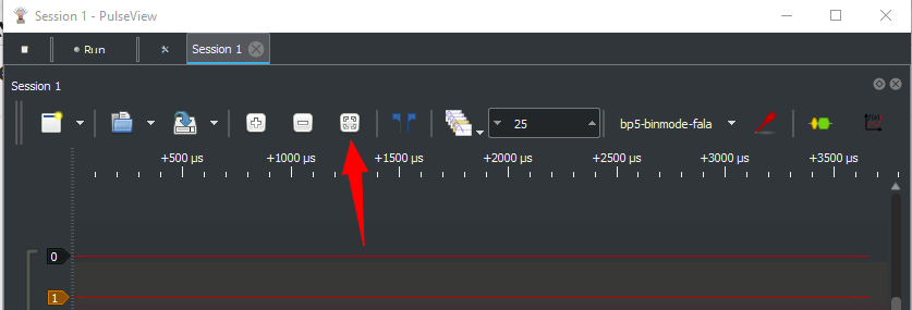
Autozoom fits all samples in the logic graph (red arrow).
Change Capture Speed
SPI> logic -o 16
Oversample rate set to: 16

Logic Analyzer settings
 Oversample rate: 16
 Sample frequency: 10000Hz

Note: oversample rate is not 1
Actual sample frequency: 160000Hz (16 * 10000Hz)

SPI>
The base capture speed or the oversample rate can can be changed with the logic command. Changing the oversample rate with the -o flag is probably easiest as the Bus Pirate will calculate the new sample frequency for you.
Limitations
This is Windows only for now. The FALA mode is not supported in the official PulseView release.
Only a few modes have been updated to work with FALA. Some modes have internal buffers that cause the logic capture to end early or even return no samples. Each mode needs a new function to indicate when all bus activity is done.
All Bus Pirate hardware supports the follow along logic analyzer, however only Bus Pirate 6 has a second buffer for the follow along mode. In earlier hardware all output pins are measured behind the IO buffer. This means the logic capture may not match the actual output of the IO buffer. This is not a problem when the Bus Pirate is used as a logic analyzer only and all pins are inputs.
Logic Analyzer System
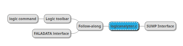
The logic command and the follow along binmode interface can be run at the same time. However, the capture buffer is shared with SUMP logic analyzer mode. SUMP and follow along logic analyzer modes cannot be used at the same time and will result in a memory error warning.