Hardware Design (6 REV 2)
The Bus Pirate is an open-source hardware debugging tool that converts simple commands into common bus protocols such as 1-Wire, I2C, SPI, UART, several LEDs and more. Send commands to a chip or sensor and get the response, without writing a line of code.
Get Bus Pirate & Accessories
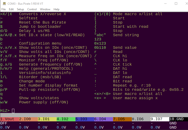
Commands are entered into a serial terminal. A new VT100 mode supports color text and a status toolbar that displays the function and voltage of each pin.
Specs
The Bus Pirate is designed to eliminate the frustrating parts of hacking and hardware tinkering. We tried to tackle all the pain points, from bizarre and uncomfortable acrobatics with multimeter probes to the hassle of connecting multiple test hooks to a single pin. With Bus Pirate 6, information you need is right where you need it.
- Follow Along Logic Analyzer - Captures logic when you send commands, instantly see what actually happened on the bus
- Bulldozer buffered IO - 1.2 to 5volt direct interfacing with 8 bidirectional buffered IOs
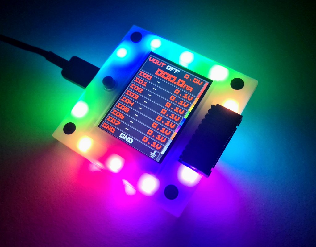
- Voltage measurement extravaganza - The Bus Pirate displays voltage readings for every pin, right on its vibrant LCD screen and in the terminal statusbar
- Current measurement - Get a reality check by monitoring current use in real time
- Programmable power supply - 1 to 5volt output, 300mA max, for powering all kinds of devices
- Programmable current limit - A 0 to 500mA programmable hardware fuse sets current limits that keep your projects safe and sane
- A big colorful display - Keep track of pin assignments, voltages and current
- Color terminal and statusbar - VT100 terminal emulation for that modern 1970s feel
- Just One Button - A dedicated button for automating repetitive debug commands while you’re wrist deep in circuits
- Auxiliary Header - A second header to easily connect logic analyzers and other tools. Stop struggling to fit multiple probe hooks on tiny chip leads
Bus Pirate 5 vs Bus Pirate v6
| Bus Pirate 6 | Bus Pirate 5 | |
|---|---|---|
| Cores | RP2350B ARM M33 x 2 | RP2040 ARM M0 x 2 |
| Speed | 133MHz | 125MHz |
| RAM | 512Kbytes | 264Kbytes |
| Flash | 128Mbits | 128Mbits |
| PIO state machines | 12 | 8 |
| Follow along logic analyzer | 8 pins | – |
| LEDs | 18 RGB LEDs | 18 RGB LEDs |
| IO pins | 8 @ 1.2-5.0volts | 8 @ 1.2-5.0volts |
| Pull-up resistors | All pins | All pins |
| Voltage measurement | All pins | All pins |
| Power supply | 1-5volts | 1-5volts |
| Current sense | 0-500mA | 0-500mA |
| Programmable fuse | 0-500mA | 0-500mA |
| Display | 320x240 IPS all-angle | 320x240 IPS all-angle |
| Flash storage | 1Gbit NAND (100MB usable) | 1Gbit NAND (100MB usable) |
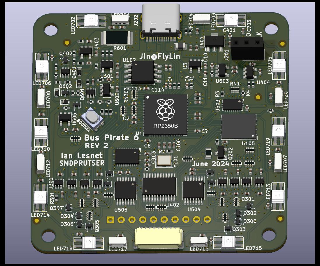
RP2350 **New in 6**
It’s like Raspberry Pi chips are designed for a Bus Pirate. Two ARM cores, cheap external flash storage - and the PIO state machines are a true hardware interface to just about any esoteric protocol. No more bit-banged software libraries!
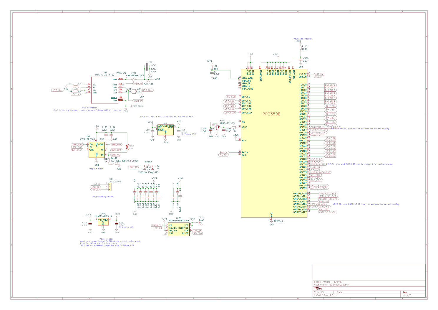
The RP2350 (U103) has a built-in bootloader that appears as a USB disk drive - just drag a firmware file into the drive to update the Bus Pirate. The bootloader is locked in ROM, there’s no chance of accidentally erasing or corrupting it. What a happy little chip!
We paired the RP2350 with a 128Mbit flash chip (U102), the maximum supported. There should be plenty of room to add features for years to come. All that space has already paid off with features like multi-language support in a single firmware release and integrated device demos.
More Pins!
RP2350B has 18 more IO pins than the RP2040 used in Bus Pirate 5. The extra pins allow us to remove the 74HC595 shift registers used on Bus Pirate 5, making room for some new features on the PCB.
ADC Expander
Live voltage measurement on every pin was an absolute feature requirement for Bus Pirate 5+. We want to to see whats happening at a glance, not perform bizarre and uncomfortable acrobatics with multimeter probes.
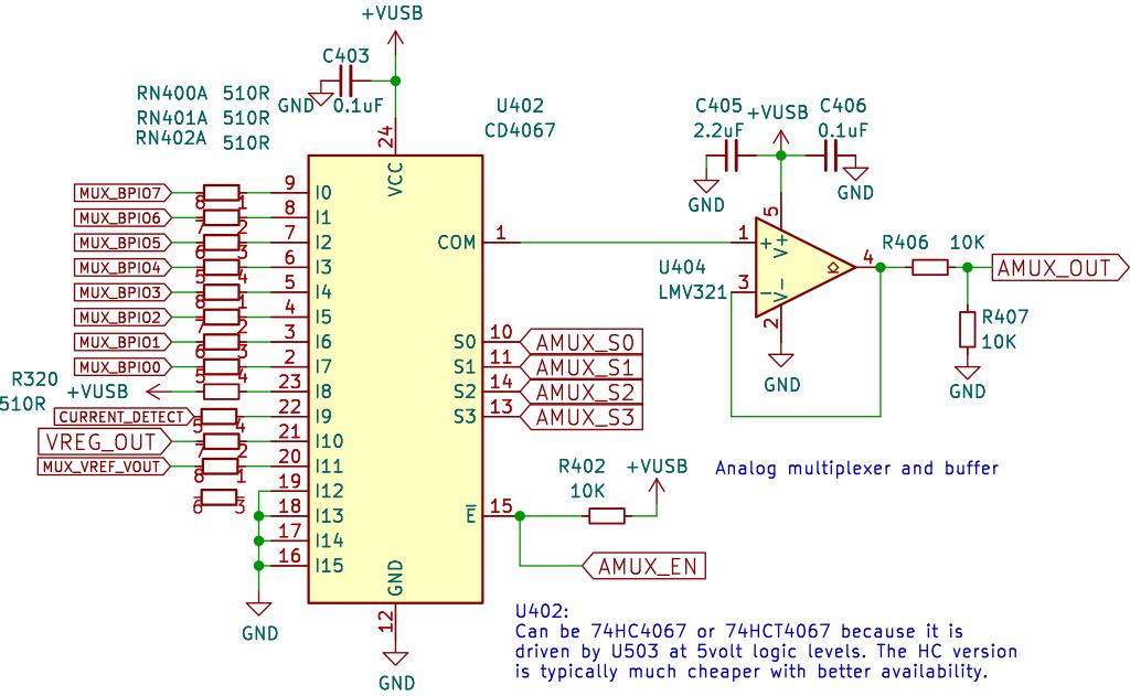
RP2350 doesn’t have enough analog to digital converter inputs for all the measurement points we need, so we added a 16 channel CD4067 analog mux (U402). The mux connects the IO pins, the programmable power supply and various test points to a single RP2350 ADC pin. All those 510R series input resistors are intended to limit back powering to tolerable levels (10mA).
An op-amp (U404) buffers the mux output and feeds a divide by two 10K resistor (R406/R407) pair. This allows the 3.3volt ADC to measure signals up to 6.6volts, however in practice the maximum voltage can not exceed the USB power supply (~5volts) without damaging other components.
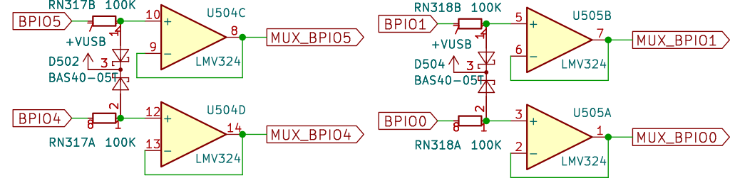
Quad op-amps (U504, U505) act as a high impedance buffer between the IO pins and analog mux.
Op-amps are pretty delicate, and tend to die if a voltage is connected while they’re not powered. Fortunately, most op-amp inputs are rated for +/-0.3volts-0.5volts from the power supply rails. We take advantage of this to limit the maximum powered-down voltage using a Schottky diode (D500, D501, D502, D503, D504) with a very low forward voltage (0.2volts @ 0.05mA) and a high value (100K) current limiting resistor (RN317, RN318). Care must be taken to choose a Shottky with low reverse current, many cheap diodes are leakier than you expect and will cause a voltage offset on floating pins.
8 IO Units
1.2-5volt Buffers
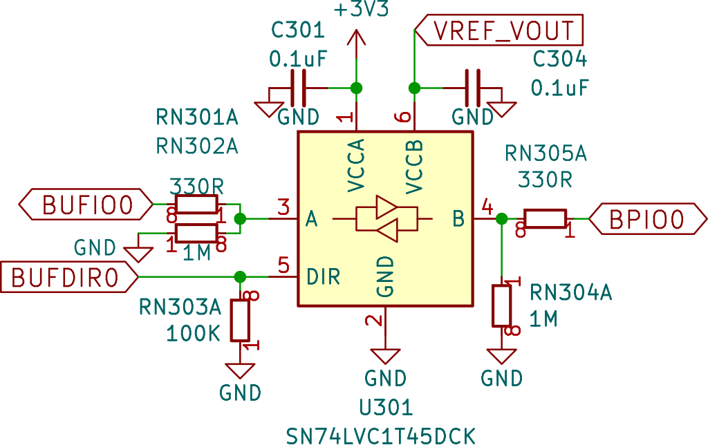
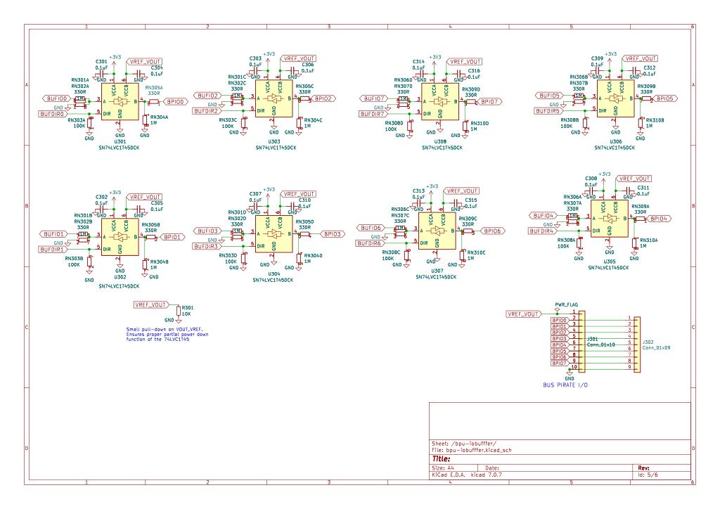
IO pins are fitted with 74LVC1T45 bidirectional buffers, we call this chip ’the bulldozer’. Half of the buffer is powered at 3.3volts to interface the RP2350. The other half is powered from the VREF/VOUT pin at 1.2-5volts to interface with the outside world. 74LVC1T45 has great specs for hacking, like 5.5volt tolerant pins and a feature that disables everything when either half of the buffer is unpowered.
Two RP2350 pins control each buffer: one sets the direction (input/output), and one does the actual IO (high/low/read). In the past this setup forced us towards a CPLD or FPGA to deal with bidirectional protocols like I2C, but the PIO peripheral does a great job of managing the buffer.
Care must be taken so the buffer and pins don’t draw excessive current from each other. This happens when both pins are set to output at the same time, one high and one low. To prevent damage we limit the maximum current draw with 120R series resistors on each 74LVC1T45 IO pin.
| Part Number | Manufacturer | Voltage Range |
|---|---|---|
| SN74LVC1T45 | Texas Instruments | 1.65-5.5volts |
| 74LVC1T45 | Diodes INC | 1.65-5.5volts |
| 74LVC1T45 | Nexperia | 1.2-5.5volts |
| AiP74LVC1T45 | WuXi I-Core | 1.2-5.5volts |
At least four manufacturers make a 74LVC1T45 with slightly different specifications. They perform similarly, but the Nexperia and I-Core parts have a wider operating range.
| Hardware Revision | Buffer Chip |
|---|---|
| 5 REV 8 | Texas Instruments |
| 5 REV 10 | WuXi I-Core |
| 6 REV 2 | WuXi I-Core |
Production Bus Pirates are fitted with buffers made by WuXi I-Core, a Chinese domestically manufactured part that operates at 1.2-5volts.
Look Behind Buffer **New in 6**
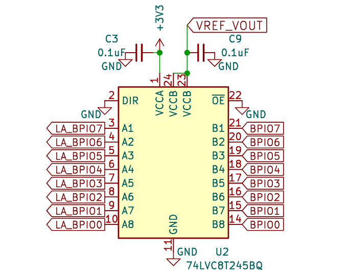
The RP2350B has 18 additional IO pins. We buffered 8 of them and connected them to the main IO pins. Now we have an integrated logic analyzer that can “look behind” the individual IO buffers to see whats actually happening in the real world.
A 74LVC8T245 buffer chip shifts the input to 3.3volts for the RP2350B. The capture side of the buffer is powered from the VREF/VOUT pin, and works from 1.2volts to 5volts. The 74LVC8T245 is specified for partial power-down applications, and is disabled when either power supply is off.
Toggleable Pull-up Resistors
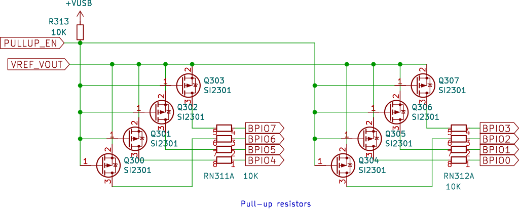
Each IO pin has a toggleable 10K pull-up resistor. Onboard pull-ups are controlled by eight SI2301 PFETs with a very low (<1volt) gate threshold voltage. Pull-ups are powered through the VOUT/VREF pin.
Eight SI2301 PFETs replace two 74HC4066 chips for pull-up control. This change lowers cost, simplifies the circuit and saves board space. They operate identically over the 74LVC1T45 operating range (1.2-5volts). However, there is a point at which each PFET will not fully turn on when VOUT/VREF is lower than the maximum gate threshold voltage (<1volt).
Main IO Connector
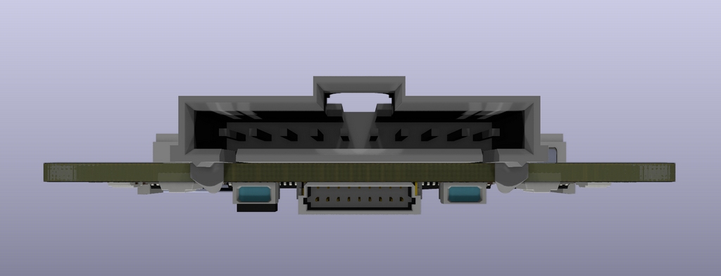
The main IO header uses a 2.54mm 10 pin TJC8A/HX25418 connector (J301). This is a keyed locking connector that works just as well with common jumper wires and 2.54mm ‘DuPont’ style connectors.
| Pin | Label | Description |
|---|---|---|
| 1 | VOUT/VREF | Pin supplies 1-5volts up to 300mA with current limit and resetable fuse (VOUT) OR connects an external voltage source to the Bus Pirate IO interface (VREF) |
| 2-9 | IO0 - IO7 | Buffered 1.2-5volt IO pins with voltage measurement and optional 10K pull-up resistors |
| 10 | GND | Ground pin |
The pinout is logical! VOUT/VREF, IO0-IO7 and Ground. Bus Pirate v3 tried so very hard to have a logical pinout, but a mis-rotated IDC connector grandfathered in a confusing pin order for nearly 15 years.
Auxiliary IO Connector
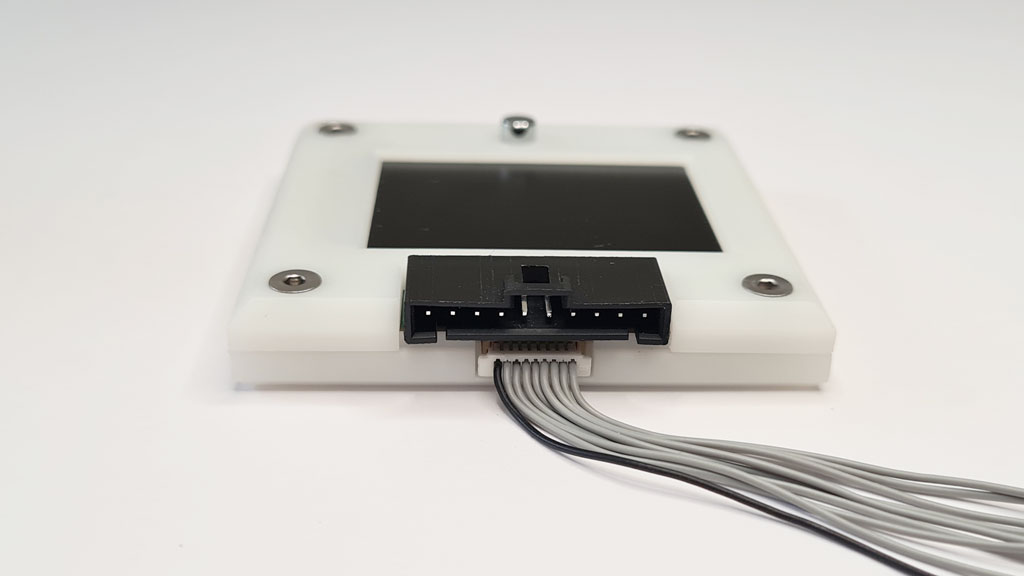
A secondary 1mm 9 pin connector (J302) under the main IO header is a tap point for a logic analyzer or other external equipment. No need to balance two or three probes on a single tiny chip lead, access the bus activity from this secondary header.
| Pin | Label | Description |
|---|---|---|
| 1-8 | IO0 - IO7 | Buffered IO pins with voltage measurement and optional 10K pull-up resistors |
| 9 | GND | Ground pin |
The 1mm 9 pin connector mates with ‘SH’ style cables.
Programmable Power Supply Unit
The bulldozer IO buffers run from 1.2 to 5volts, they need a power supply to match. The programmable power supply unit is another killer feature of the Bus Pirate.
- 1-5volts adjustable output, 300mA max
- 0-500mA current sense
- 0-500mA current limit with digital fuse
- Backflow prevention to protect the PPSU when an external voltage is applied to the VREF/VOUT pin
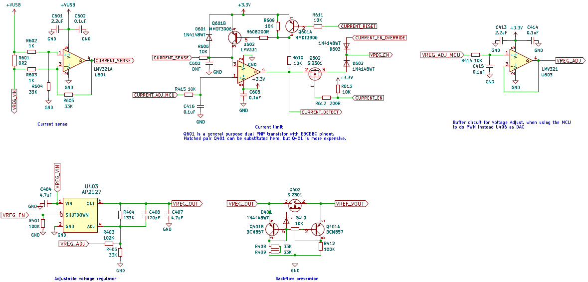
Adjustable Output 1 to 5volts
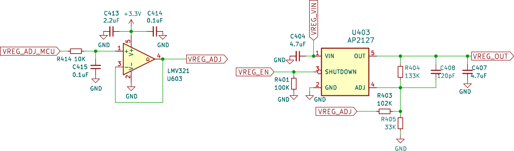
The heart of the programmable power supply is a 0.8 to 5volt adjustable output voltage regulator (U403). Normally fixed resistor values set the output voltage of an adjustable regulator, but we’ve given it programmable output by margining the feedback pin with a pulse width modulator. The PWM output of the RP2350 is filtered through a 10K resistor (R414) and 100nF capacitor (C415), then buffered with an op-amp (U603).
Older adjustable voltage regulators typically have a range from 1.25 to 5volts or more. A newer class of regulators go a bit lower - down to 0.8volts.
We worked with two regulators during development: MCP1824 from Microchip, and AP2127 from Diodes INC. They have the same pinout and similar specs, but the MCP1824 has a 0.41volt reference while the AP2127 has a 0.8volt reference. We prefer the MCP1824 because the reference value makes it easier to select common resistors for the margining circuit, but it has become expensive and at times hard to find.
0.8-5volts is the voltage regulator range, but the PFET used in the backflow prevention circuit may not turn on when the output is less than the gate threshold voltage (1volt max). The average gate threshold for the SI2301 in REV10 is <0.4volts, but that is not guaranteed, the Vgth will vary. For this reason, the Bus Pirate power supply is specified for 1-5volts output, but you might just get lucky!
300mA is the rated maximum of the voltage regulator, but we added some headroom in the current limit circuit to account for current spikes.
| Part | Ideal Value | Closest Value | ||||
|---|---|---|---|---|---|---|
| R403 | R404 | R405 | R403 | R404 | R405 | |
| MCP1824 | 77.96K | 99.22K | 10K | 78K | 100K | 10K |
| AP2127 | 103.13K | 131.25K | 33K | 102K | 133K | 33K |
MCP1824 and AP2127 are similar, but each has a different reference voltage. R403/R404/R405 need to match the regulator as shown in the table.
A common 1.25V-5V adjustable regulator can be used with the correct resistor values (see calculations spreadsheet). The Bus Pirate will lose features though. The output range will be limited to 1.25volts to 5volts, instead of ~1volts to 5volts.
Current Sense
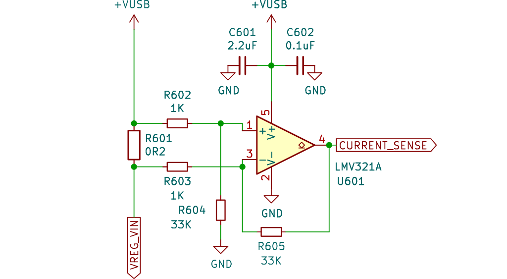
Current consumption can be used as a proxy to debug a circuit. Is there a short? Is this chip even running? This is certainly evident in the Shenzhen mobile phone repair markets where current meters taped into cardboard boxes are the go-to tool for diagnosing iPhone motherboard failures.
A 200m resistor (R601) causes a slight voltage drop in proportion to the current passing through it. An op-amp (U601) amplifies the difference approximately 32 times, scaling 0-500mA current use to 0-3.3volt output that we can measure with the RP2350 ADC.
Current sense is measured with a dedicated RP2350 ADC pin instead of passing through the analog multiplexer. This is because the mux is followed by a voltage divider that would cut the measurement resolution in half. That wouldn’t be fair to our hard working little op-amp!
Production Bus Pirates use an ‘A’ graded op-amp with lower maximum input offset (0.1mV typical, 0.4mV max @25C -vs- 0.4mV typical, 3.5mV max @25C) for improved current measurement accuracy.
Programmable 0-500mA Current Limit
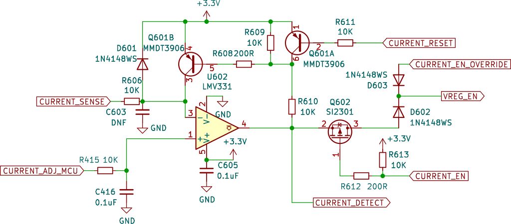
Since we’ve already got current consumption scaled to a 0-3.3volt output signal, wouldn’t it be cheeky to pop a comparator behind it to make a programmable fuse?
The scaled current sense output hits the comparator (U602) on the - pin. The limit is set with another filtered (R415/C416) pulse width modulator output to the comparator + pin. When the current sense voltage on the - pin exceeds the limit set by the PWM on the + pin, the output (VREG_EN) inverts which disables the voltage regulator.
This doesn’t quite get us there. When the voltage regulator disables current use drops, causing the comparator to flip back on. This creates a loop where the VREG oscillates on and off. That’s definitely not what we want.
A PNP transistor pair (Q601A/B) and a few passive parts capture the inversion and hold the comparator in the off state. The PNP pair sustains a current path through the two transistors until it is forcibly changed by an outside voltage (CURRENT_RESET).
A PFET (Q602) connected to a 74HC595 pin (CURRENT_EN) enables/disables comparator control of the voltage regulator. Two diodes (D602/D603) create a logical OR with another 74HC595 pin (CURRENT_EN_OVERRIDE) so the current limit can be overridden completely.
There you have it, a programmable fuse with just a couple extra parts.
300mA is the rated maximum of the voltage regulator, but we added some headroom in the current limit circuit to account for current spikes.
Backflow Prevention
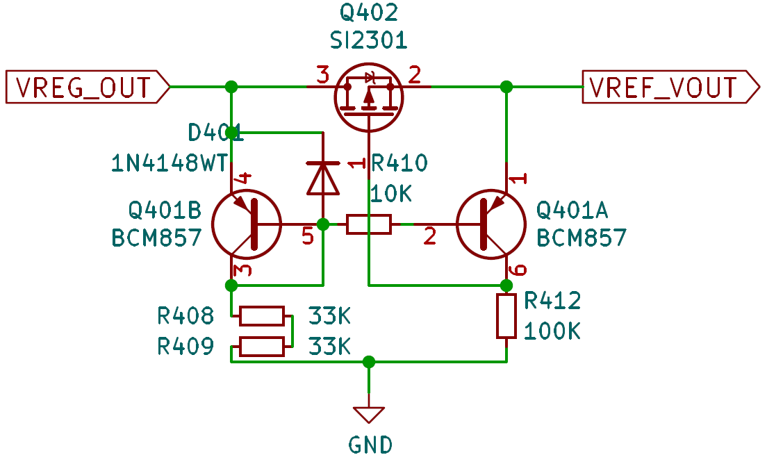
A backflow prevention switch helps protect all the little analog bits when an external voltage is applied to the VOUT/VREF pin. A closely matched PNP pair (Q401A/B) creates a current mirror that controls a P-channel MOSFET (Q402) high-side switch. When the voltage on VREF/VOUT is greater than the voltage in the PPSU, the PFET turns off.
The Bus Pirate monitors the voltage on both sides of the PFET, and displays a warning when VREF_VOUT is greater than VREG_OUT.
| Symbol | Parameter | Conditions | Min | Typ | Max | Unit |
|---|---|---|---|---|---|---|
| hFE1/hFE2 | hFE matching | VCE=-5V; IC=-2mA | 0.9 | 1 | - | - |
| VBE1-VBE2 | VBE matching | VCE=-5V; IC=-2mA | - | - | 2 | mV |
Q401 requires a closely matched PNP transistor pair. The hFE of the transistor pair should differ by no more than 10%, and the VBE should differ no more than 2mV.
While the adjustable voltage regulator is capable of 0.8 to 5.0volt output, the gate threshold of the PFET determines the minimum output. Common inexpensive PFETs generally have a maximum gate threshold of -1volt or more, and therefore may not fully turn on in the 0.8-1volt range.
R408/R409 are two 33K resistors instead of a single resistor. This was done to reduce the number of parts in the BOM and save a pick and place feeder during development.
1Gbit NAND Flash
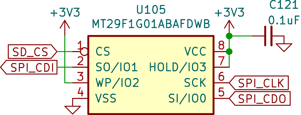
A 1 Gbit NAND flash chip is connected to the RP2350 via an SPI bus shared with the LCD and 74HC595 IO expanders. NAND flash is cheap and commonly used in removable storage, but it’s also messy and prone to error. Bad block detection/marking and wear leveling all need to be managed in the RP2350 or the chip will die an untimely death.
NAND flash is used to save global and mode configuration in simple JSON files. It can also be used for all kinds of interesting things, like firmware storage for production programming, saving dumps from flash chips and EEPROMs or logging bus communications.
NAND flash appears as a readable and writable USB disk drive, however the speed is quite low because there are only enough RP2350 pins to implement a one bit SPI interface.
LCD
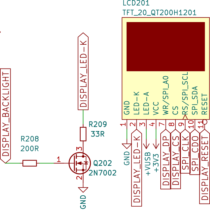
A beautiful 240x320 pixel color IPS (all angle viewing) LCD acts as a pin label, displays the voltage on each pin and shows the current consumption of the programmable power supply unit. The LCD shares an SPI bus with the NAND flash and 74HC595 IO expanders. The display is already FCC certified, which doesn’t exempt us from certification, but a bad LCD can spray radiation all over the spectrum causing us to fail.
The LCD background image is a bitmap converted to a C byte array and included in the firmware. Several open source font sets were converted to bitmaps for the display.
18 RGB LEDs
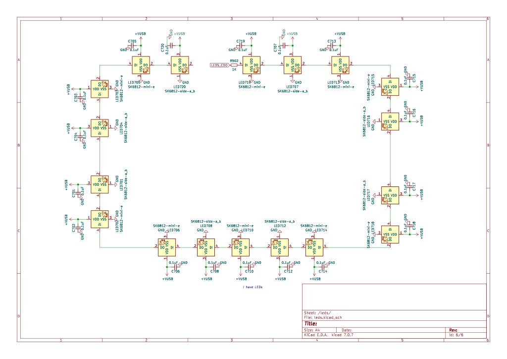
It’s customary to have an indicator LED, so to check that box we added 18 SK6812 RGB LEDs. SK6812s are controlled by a time-based protocol that can be a real pain to work with, but the RP2350 PIO module makes it a breeze. The LEDs are powered directly from USB voltage (~5volts), and require a 5volt input signal. The RP2350 3.3volt output is converted to 5volts using one pin of the 74HCT245 level shifter.
SK6812s are found in cheap LED strips. They’re common, inexpensive and come in a variety of interesting form factors. 10 MINI-E packaged LEDs shine up through holes in the PCB to illuminate the case around the LCD. 8 SIDE-A LEDs along the edge of the board have an under lighting effect.
There are two common footprints for SK6812-SIDE-A. The preferred part has evenly spaced pads that bend 90 degrees and extend up the back of the case. We have had the best success reflow soldering this footprint, and it is MUCH easier to hand rework than others.
You might be thinking: 18 LEDs x 3 colors x 20mA is too much current for USB! You’d be totally right! Great care is taken in the firmware to ensure that the maximum current stays within the allowable limits for USB.
If you go hardware hacking, be aware that it is possible to far exceed the limits of your USB port when the LEDs are turned on at 100% brightness. It does look really cool though.
Just One Button
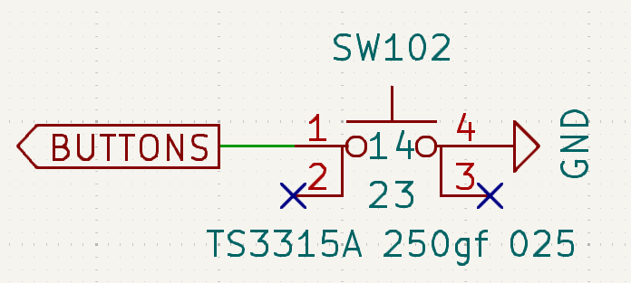
18 party LEDs, but just one button! The button is scriptable and automates repetitive tasks such as production firmware programming. It’s also used to escape from modes where the Bus Pirate would otherwise need to be reset, such as a transparent UART bridge.
Interactive BOM
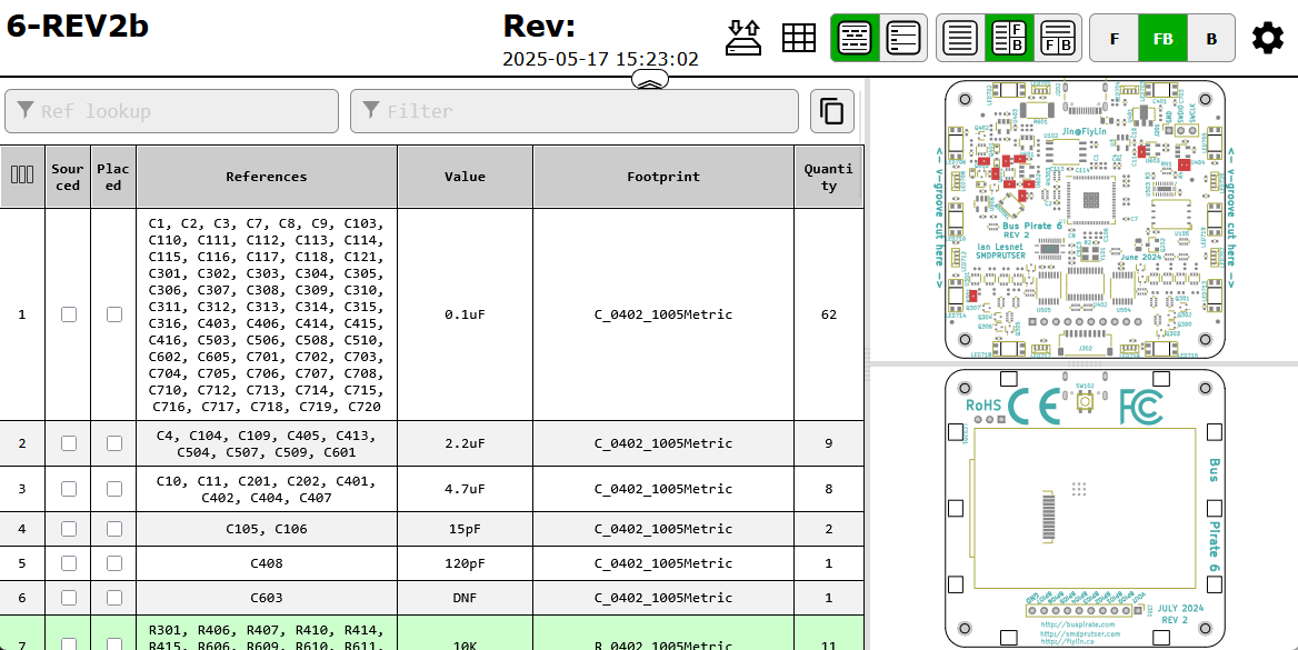
- Interactive BOM. Created with Interactive HTML BOM plugin for KiCad.
- Schematic (PDF)
- Component placement (PDF)
Get a Bus Pirate 6
Get Bus Pirate & Accessories
- Browse Complete Bus Pirate hardware collection
- Bus Pirate 5 REV10 with enclosure
- Probe Cable Kit
- Auxiliary Cable Kit
- Quick Connect Adapter
More Documentation
Here’s some other fun stuff you might enjoy.
- Component selection and sourcing
- Cables and Milled breadboard pins
- Injection molded case
- Hardware users guide
- Getting started and Command reference
- Firmware development and translation
- Manufacturing resources