WS2812/SK6812/NeoPixel LED
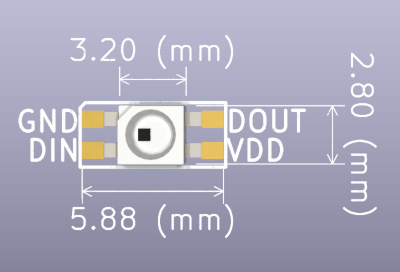
| Pin | Description | Pin | Description |
|---|---|---|---|
| GND | Ground | DOUT | Data Output to next LED |
| DIN | Data Input | VDD | 5 volt power supply |
WS2812, SK6812, and ‘NeoPixel’ RGB LEDs are all controlled by the same single-wire, time-based protocol. Multiple LEDs can be chained together, with the DOUT of one LED connecting to the DIN of the next.
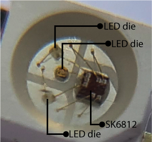
3 LED dies (red, blue, green) and an controller chip are bonded to a bit of metal called a leadframe. The leadframe is put inside a casing and covered in epoxy. Then the whole thing is baked, like a cake. Technically we should call the device a pixel, because it contains multiple LEDs.
Protocol
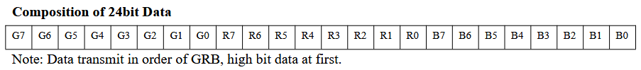
The WS2812 protocol is a single-wire, time-based protocol. The data is sent as a series of 24-bit RGB values, with each color represented by 8 bits. The data is sent in the order of green, red, and blue (GRB).
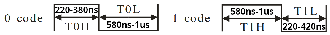
Single wire protocols like the WS2812 are generally time based. 0 is encoded as a short high followed by a long low. 1 is encoded as a long high followed by a short low. The timing of the high and low signals is critical to the operation of the protocol.
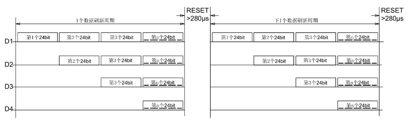
Each LED in the chain receives data and passes it on to the next LED. A >280us low signal, called reset, must separate each LED update.
Images via datasheet.
Connections
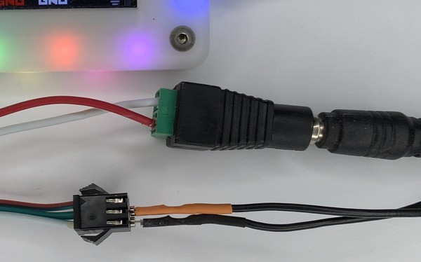
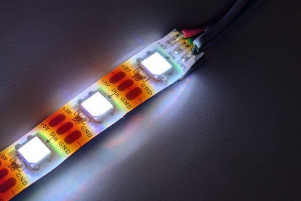
Many strips of WS2812s come with connectors already soldered for external power and data. You may need to pull back the heatshrink over the connector wires to determine the pinout.
Our strip has a 3 pin data connector with +5volts, data, and ground. Two additional wires are available for external power, which we connected to a screw terminal barrel jack socket.
External power
If using a strip of more than 5 WS2812s, you must use an external 5 volt power supply.
| External 5 volt power supply | WS2812 | Description |
|---|---|---|
| +5 volts | VDD | Power to the WS2812 |
| GND | GND | Ground connection to the WS2812 |
WS2812s generally come in a strip of multiple devices. RGB LEDs can consume a lot of current, up to 60mA per device when all the dies are powered. When using a string of more than 5 devices, you must use an external power supply.
If your strip is very small (<5 LEDs), you can get away with powering the LEDs from the Bus Pirate VOUT pin.
Data
| Bus Pirate | WS2812 | Description |
|---|---|---|
| SDO | DIN | Data from Bus Pirate to first LED |
| GND | GND | A ground connection is required |
Connect the Bus Pirate SDO pin to the WS2812 DIN wire, and Bus Pirate ground to WS2812 ground.
Don’t forget a ground connection, even if the strip is powered by an external supply.
Setup
HiZ> m led

Mode: LED
LED type
 1. WS2812/SK6812/'NeoPixel' (single wire interface)*
 2. APA102/SK9822 (clock and data interface)
 3. Onboard LEDs (18 SK6812s)
 x. Exit
Type (1) > 1
LED-(WS2812)> W 5
5.00V requested, closest value: 5.00V
300.0mA requested, closest value: 300.0mA

Power supply:Enabled
Vreg output: 5.0V, Vref/Vout pin: 5.0V, Current: 2.6mA

LED-(WS2812)>
Setup is easy, enter LED mode and enable a 5 volt power supply.
m led- set the Bus Pirate to LED mode, choose WS2812 as the interface typeW 5- set the onboard power supply to 5 volts to power the Bus Pirate buffers
Even if the LEDs are powered by an external supply, the Bus Pirate buffers must be powered or the data signal will not be sent.
See it in action
Green, red, blue
LED-(WS2812)> [ 0xff0000 0x00ff00 0x0000ff

RESET
TX: 0xFF0000.24 0x00FF00.24 0x0000FF.24
LED-(WS2812)>
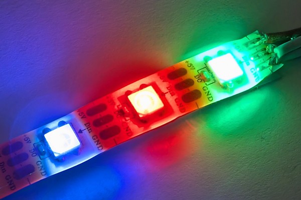
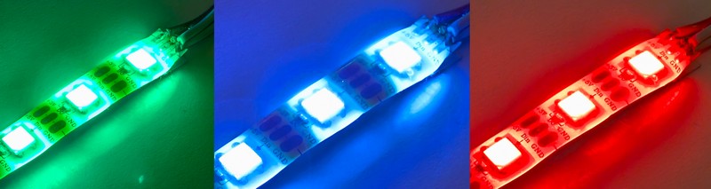
Let’s light the first three LEDs in the chain. The first LED will be green, the second red, and the third blue.
[- WS2812 data frames start with a reset (>280us low),[sends reset in LED/WS2812 mode.0xff0000- set the first WS2812 to green/full brightness0x00ff00- set the second WS2812 to red/full brightness0x0000ff- set the third WS2812 to blue/full brightness
[ sends a reset signal to the WS2812. The reset signal is >280us low. We could accomplish the same 280us delay with the command d:280, the [ command is just a shortcut.
Purple
LED-(WS2812)> [ 0x00FFFF:3

RESET
TX: 0x00FFFF.24 0x00FFFF.24 0x00FFFF.24
LED-(WS2812)>
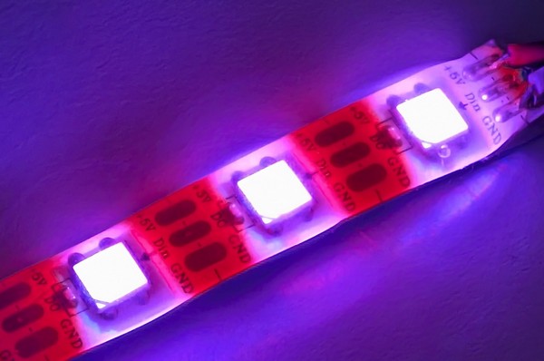
Next let’s mix colors to make all three LEDs purple.
[- WS2812 data frames start with a reset (>280us low),[sends reset in LED/WS2812 mode.0x00ffff:3- set blue and red to full brightness, green to 0.:3repeats the command 3 times, so all three WS2812s are set to purple.
RGB cycle
LED-(WS2812)> [0xff0000:3  D:500 [0x00ff00:3 D:500 [0x0000ff:3

RESET
TX: 0xFF0000.24 0xFF0000.24 0xFF0000.24
Delay: 500ms
RESET
TX: 0x00FF00.24 0x00FF00.24 0x00FF00.24
Delay: 500ms
RESET
TX: 0x0000FF.24 0x0000FF.24 0x0000FF.24
LED-(WS2812)>
We can use the Bus Pirate delay command to create a simple RGB cycle.
[- WS2812 data frames start with a reset (>280us low),[sends reset in LED/WS2812 mode.0xff0000:3- set three WS2812s to green/full brightness.D:500- delay 500ms.[ 0x00ff00:3 D:500- set three WS2812s to red/full brightness, delay 500ms.[ 0x0000ff:3- set three WS2812s to blue/full brightness.
White
LED-(WS2812)> [ 0xffffff:3

RESET
TX: 0xFFFFFF.24 0xFFFFFF.24 0xFFFFFF.24
LED-(WS2812)>
To aproximate white, we can set all three colors to full brightness.
[- WS2812 data frames start with a reset (>280us low),[sends reset in LED/WS2812 mode.0xffffff:3- set three WS2812s to white/full brightness.
Off
LED-(WS2812)> [ 0x000000:3

RESET
TX: 0x000000.24 0x000000.24 0x000000.24
LED-(WS2812)>
To turn off the LEDs, we can set all three colors to 0.
[- WS2812 data frames start with a reset (>280us low),[sends reset in LED/WS2812 mode.0x000000:3- set three WS2812s to off.