TCS3472x color sensor I2C
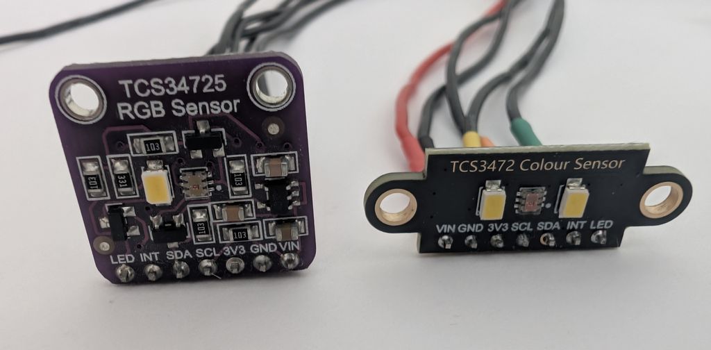
TCS3472x series color sensors measure the amount of red, green, blue, and clear light hitting the sensor. They are often used in mobile phones and other devices to measure ambient light levels, or to detect colors for sorting or quality control. They’re intended to be located under dark glass, but you’ll most likely find them on a breakout board with an onboard LED to illuminate the object being measured.
Get Bus Pirate & Accessories
Connections
| Bus Pirate | TCS3472x | Description |
|---|---|---|
| SDA | SDA | I2C Data |
| SCL | SCL | I2C Clock |
| Vout/Vref | VDD (VIN) | 3.3volt power supply |
| GND | GND | Ground |
These sensors are tiny and it’s highly likely you’re using a breakout board, like us. The important connections are the I2C data (SDA) and clock (SCL) lines, the power supply (Vout/Vref), and ground (GND).
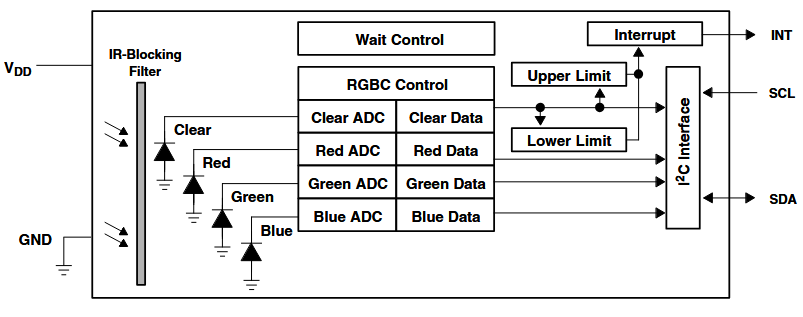
Image source: ams-OSRAM TCS3472x Datasheet.
Breakout Boards
There are several TCS3472x breakout boards available, many are based on Adafruit’s design. Here’s some common, but not guaranteed, pin functions:
- VIN is generally a 3.3-5 volt power supply pin with 3.3v regulator to supply the sensor
- 3V3 is either a 3.3v supply input, or output from onboard regulator if VIN is powered
- LED controls the onboard LED(s). Normally the LED is on, hold this pin to ground to turn the LED off
- INT is an interrupt output pin from the sensor, not used in this demo
These sensors are intended to be behind dark glass. Using it in free air on a breakout board with a low quality white LED in close proximity is really inconsistent. Often the color measurement looked more like the glare of the LED. The board with 2 LEDs was unusable, go for a board with one LED if possible.
See it in action
Setup
HiZ> m i2c

Mode: I2C
I2C speed
 1kHz to 1000kHz
 x. Exit
kHz (400kHz*) > 400
Clock stretching
 1. OFF*
 2. ON
 x. Exit
OFF (1) > 1
I2C>
This sensor has an I2C interface, put the Bus Pirate in I2C mode.
m i2c- set the Bus Pirate to I2C mode, or just hitmto select from the menu.400- set the I2C bus speed to 400kHz.1- disable clock stretching.
Power supply
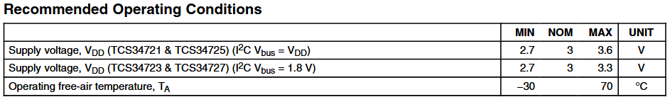
There are several versions of the TCS3472x series sensors, breakout boards generally have the TCS34725. The safe voltage range for all versions is 2.7 to 3.3 volts.
I2C> W 3.3
3.30V requested, closest value: 3.30V
300.0mA requested, closest value: 300.0mA

Power supply:Enabled
Vreg output: 3.3V, Vref/Vout pin: 3.3V, Current: 3.9mA

I2C>
Let’s set the Bus Pirate to power the chip at 3.3 volts, a very common voltage for current generation I2C devices.
W 3.3- enable the onboard power supply at 3.3 volts with the default 300mA current limit.
Pull-up resistors
I2C> P
Pull-up resistors: Enabled (10K ohms @ 3.3V)

I2C>
I2C is an open collector output bus, the Bus Pirate and the chip can only pull the line low to 0 (ground). A pull-up resistor is needed to pull the line high to 1 (3.3 volts). The Bus Pirate has built-in pull-up resistors that can be enabled with the P command.
P- Enable the onboard pull-up resistors.
Be sure to enable the pull-up resistors. Without them, the clock data line will never go high and you’ll read only 0s.
I2C address scan
I2C> scan
I2C address search:
0x29 (0x52 W) (0x53 R)

Found 2 addresses, 1 W/R pairs.

I2C>
We need the correct I2C address to talk to the sensor. We could look in the datasheet, or we can run the handy I2C address scanner.
scan- Scan the I2C bus for devices
The scanner found an I2C device at address 0x29 (0x52 write, 0x53 read).
If the scanner doesn’t find the device, ensure the power supply is enabled W 3.3 and the pull-up resistors are enabled P.
Configuration
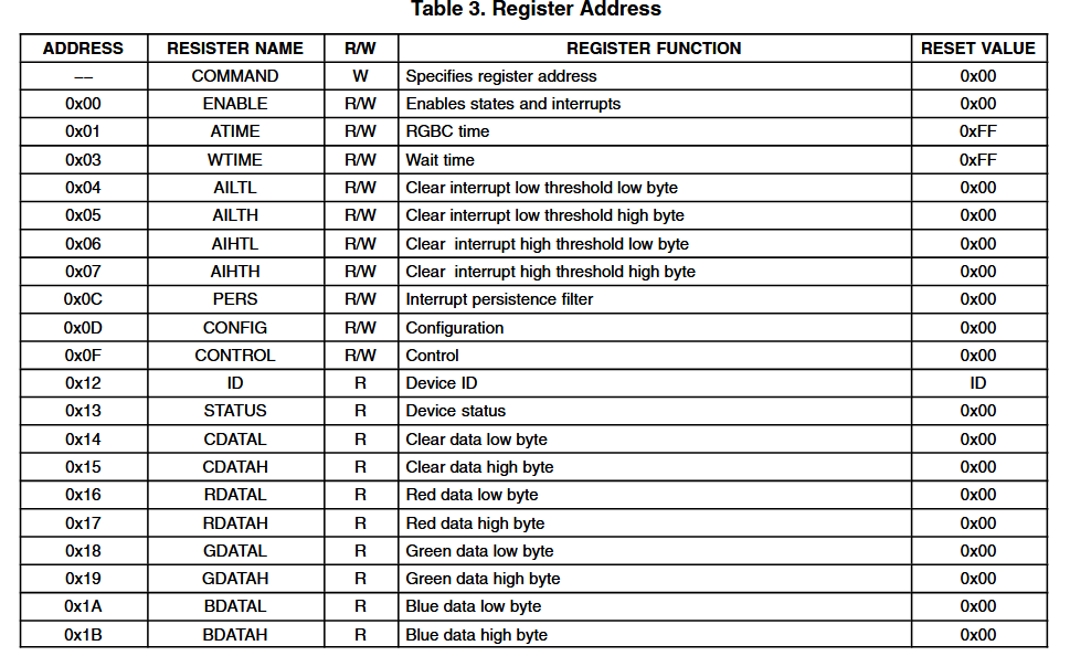
TCS3472x has several byte sized registers that configure the device and store the color measurements. We’re going to be looking at the following registers:
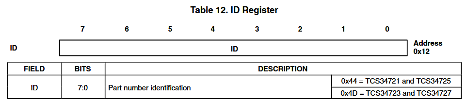
- ID Register (0x12) - Contains the device ID, used to confirm the device is working.
- Enable Register (0x00) - Controls the internal clock and color sensing element.
- Control Register (0x0F) - Controls the gain of the color sensing element.
- Wait Time Register (0x03) - Configures the time between measurements.
- RGBC Timing Register (0x01) - Controls the integration time of the color sensing element.
- Color Data Registers (0x14 to 0x1B) - Stores the color measurements in clear, red, green, and blue channels.
Command Register
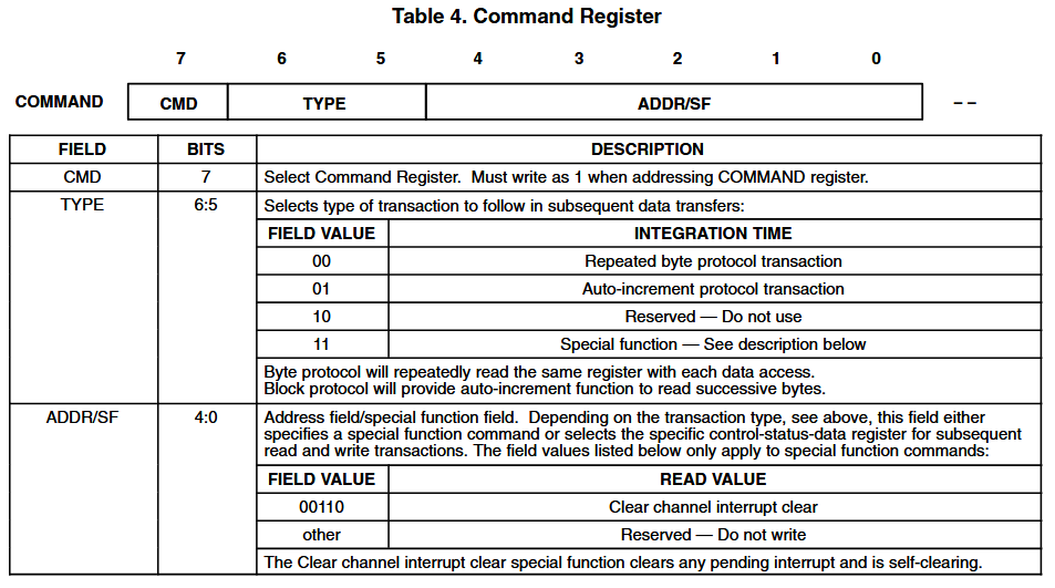
The command register is used to access the other registers. The 7th bit of the command register is always set to 1, the address of the register to access is set in bits 4:0. To access register 0x01, for example, we write 0b10000001 (0x81) to the command register. The 7th bit is set to 1, and the lower 5 bits are the register address (0b00001 = 0x01).
Read ID Register (0x12)
Let’s read the ID register to confirm the device is working. The ID register is at address 0x12.
I2C> = 0x12
 =0x12 =18 =0b00010010
I2C> = 0b10010010
 =0x92 =146 =0b10010010
I2C>
To access the ID register, we need to write the register address to the command register with the 7th bit set to 1.
- 0x12 = 0b0001'0010 - First convert the register address to binary
- 0b1001'0010 = 0x92 - Set the 7th bit to 1, then convert back to hexadecimal
You can write the command register in binary (starts with 0b) or hexadecimal (starts with 0x). We’ll stick with binary for the rest of this demo.
I2C> [0x52 0b10010010 [0x53 r]

I2C START
TX: 0x52 ACK
TX: 0b10010010 ACK
I2C REPEATED START
TX: 0x53 ACK
RX: 0x44 NACK
I2C STOP
I2C>
Read the ID register with the typical I2C pattern: write the location to read to the write address, then read data from the read address.
[- I2C START bit, starts an I2C transaction0x52- Write the TCS3472x I2C write address (0x52) to the bus0b10010010- Write the ID register address 0x12 with the 7th bit set to 1[- I2C repeated START bit, starts a new I2C transaction0x53- Write the TCS3472x I2C read address (0x53)r- Read one byte from the ID register]- I2C STOP bit, ends the I2C transaction
The ID register contains 0x44.
| Part | I2C Address | I2C bus voltage | ID Register |
|---|---|---|---|
| TCS34721 | 0x39 (0x72 write, 0x73 read) | VDD | 0x44 |
| TCS34723 | 0x39 (0x72 write, 0x73 read) | 1.8 V | 0x4D |
| TCS34725 | 0x29 (0x52 write, 0x53 read) | VDD | 0x44 |
| TCS34727 | 0x29 (0x52 write, 0x53 read) | 1.8 V | 0x4D |
There are four variants of the TCS3472x series sensors. The 1 and 3 versions are a custom order part with an alternate I2C address, it’s unlikely to be found outside some very specialized equipment.
The 5 version is by far the most common on small breakouts from your favorite online retailer. The 7 version has a special low voltage I2C bus separate from the power supply, you might find these in mobile phones and other devices with a low voltage I2C bus.
With ID register 0x44 and I2C address 0x29 (0x52 write, 0x53 read), we have a common TCS34725 on this inexpensive breakout board.
Enable Register (0x00)
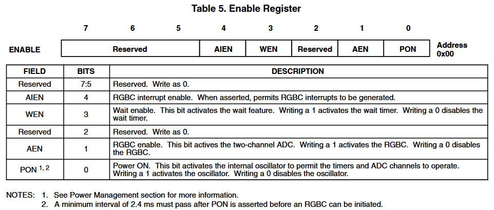
The enable register controls the internal clock (bit 0, PON) and the color sensing element (bit 1, AEN). These need to be enabled before we can read color data. The enable register is at address 0x00.
See footnote 2 at the bottom of the register description? A minimum interval of 2.4 milliseconds is required between enabling the oscillator and the sensor. We’re going rogue here and we’ll follow the datasheet. Every open source driver we’ve seen ignores this and enables both at the same time, which also seems to work.
I2C> [0x52 0b10000000 0b1] D:3 [0x52 0b10000000 0b11]

I2C START
TX: 0x52 ACK
TX: 0b10000000 ACK 0b00000001 ACK
I2C STOP
Delay: 3ms
I2C START
TX: 0x52 ACK
TX: 0b10000000 ACK 0b00000011 ACK
I2C STOP
I2C>
We’re going to enable the oscillator first by setting bit 0 to 1. After a >2.4ms delay, we’ll enable the color sensing element by setting bit 1 to 1.
[0x52 0b10000000 0b1]- Write the enable register address 0x00 with the 7th bit set to 1, then set bit 0 to 1 to enable the oscillator.D:3- Wait for 3 milliseconds to allow the oscillator to stabilize.[0x52 0b10000000 0b11]- Write the enable register address 0x00 with the 7th bit set to 1, then set bit 1 to 1 to enable the color sensing element.
When entering binary numbers, you can leave out any leading 0s. For example, 0b00000001 is the same as 0b1, and 0b00000011 is the same as 0b11.
Control Register (0x0F)
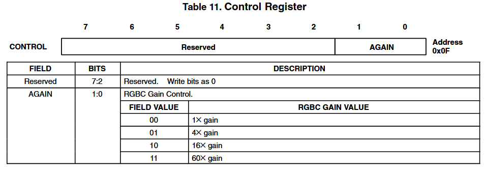
Bits 0 and 1 of the control register (0x0F) control the gain of the color sensing element. The gain can be set to 1x, 4x, 16x, or 60x. Higher gain allows the sensor to measure lower light levels, but also increases noise.
Most of the TCS3472x breakouts have a onboard LED that illuminates the object being measured. Through experimentation we’ve found that 16x gain (0b10) gives fairly usable results. If your color measurement data is all close to 0xffff, try decreasing the gain to 4x or 1x. If your data is all close to 0x0000, try increasing the gain to 60x.
I2C> [0x52 0b10001111 0b10]

I2C START
TX: 0x52 ACK
TX: 0b10001111 ACK 0b00000010 ACK
I2C STOP
I2C>
Configure the control register (0x0F) to use 16x gain (0b10).
[0x52 0b10001111 0b10]- Write the control register address 0x0F with the 7th bit set to 1, then set the gain to 16x (0b10).
Wait Time Register (0x03)
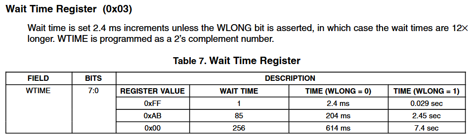
The wait time register configures the time between measurements. For low power light ambient light sensing, for example in a mobile phone, this value could be set as long as possible to conserve the battery.
We’re not on a battery budget, so let’s configure the minimum wait time possible (2.4ms, 0xff). The wait time register is at address 0x03.
I2C> [0x52 0b10000011 0xff]

I2C START
TX: 0x52 ACK
TX: 0b10000011 ACK
TX: 0xFF ACK
I2C STOP
I2C>
Configure the wait time register (0x03) to use the minimum wait time of 2.4ms (0xFF).
[0x52 0b10000011 0xff]- Write the wait time register address 0x03 with the 7th bit set to 1, then set the wait time to 2.4ms (0xff).
RGBC Timing Register (0x01)
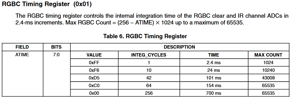
The TCS3472x has four integrating analog to digital converters that measure the amount of red, blue, green, and clear light hitting the sensor. The RGBC timing register controls the integration time - longer integration times produce less noisy measurements.
We’re going to use the maximum integration time (0x00) for the best possible measurements. Each measurement will take 700ms. That’s far too slow for automated sorting or quality control, but perfect for our demo. The RGBC timing register is at address 0x01.
We noticed that the gain setting will not take effect until the RGBC timing register is set. If you change the gain setting, be sure to set the RGBC timing register afterwards.
I2C> [0x52 0b10000001 0x00]

I2C START
TX: 0x52 ACK
TX: 0b10000001 ACK
TX: 0x00 ACK
I2C STOP
I2C>
Configure the RGBC timing register (0x01) to use the maximum integration time of 700ms (0x00).
[0x52 0b10000001 0x00]- Write the RGBC timing register address 0x01 with the 7th bit set to 1, then set the integration time to 700ms (0x00).
Read Color Data (0x14 to 0x1B)
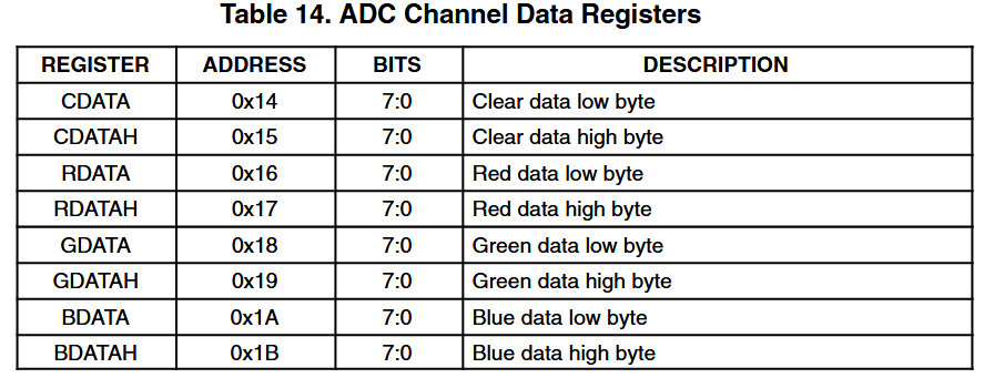
As the analog to digital converters measure clear, red, green, and blue light, they store the results in registers 0x14 to 0x1B. Measurements are 16-bit unsigned values (0 to 65,536) stored in two 8 bit registers.
I2C> [0x52 0b10010100 [0x53 r:8]

I2C START
TX: 0x52 ACK
TX: 0b10010100 ACK
I2C REPEATED START
TX: 0x53 ACK
RX: 0x07 ACK 0xCB ACK 0x0B ACK 0x81 ACK 0xB7 ACK 0x27 ACK 0x5F ACK 0x27 NACK

I2C STOP
I2C>
We can, and should, read all the color data in one I2C transaction. The TCS3472x is designed so that the ADCs won’t update the registers while we’re reading them to avoid corrupt data.
[0x52 0b10010100][0x53 r:8]- Write the color data register address 0x14 with the 7th bit set to 1, then read 8 bytes from the TCS3472x I2C read address.
| Measurement | Clear | Red | Green | Blue |
|---|---|---|---|---|
| Value | 0xCB07 | 0x810B | 0x27B7 | 0x27F5 |
| Decimal | 51975 | 33035 | 10167 | 10229 |
| Percent (/65536) | 79.3% | 50.4% | 15.5% | 15.6% |
The eight bytes returned are the clear, red, green, and blue measurements in that order. The first byte is the lower 8 bits of the measurement, the second byte is the upper 8 bits.
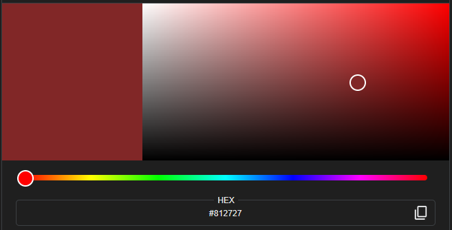
Since most web color pickers and RGB LEDs use 8 bit color values, we’ll just use the high byte of each measurement (R: 0x81, G: 0x27, B: 0x27) to represent our color. Find an online color picker and enter the RGB value as a hexadecimal color code (0x812727). This is a fairly good match to the cheap red multimeter under the sensor.
The 16x gain setting should make the upper byte of each measurement fairly representative of the color intensity, though you may need to experiment to suit your breakout board.
tsc3472 command
The tsc3472 command configures and reads a TCS3472x color sensor, then displays the color on the Bus Pirate LEDs. Default gain is 16x, default integration cycles is 256.
I2C> tcs3472 -h
usage:
tcs3472 [-g <gain:1,4,16*,60x>] [-i <integration cycles:1-256*>] [-h(elp)]
- read tcs3472x color sensor, show colors in terminal and on Bus Pirate LEDs
- 3.3volt device, pull-up resistors required
Read with default* 16x gain, 256 integration cycles: tcs3472
Read with 60x gain, 10 integration cycles: tcs3472 -g 60 -i 10

I2C>
| Flag | Description |
|---|---|
| -g | Set the gain to 1x, 4x, 16x, or 60x. Default is 16x. |
| -c | Set the number of integration cycles to 1-256. Default is 256. |
Get a Bus Pirate
Get Bus Pirate & Accessories
- Browse Complete Bus Pirate hardware collection
- Bus Pirate 5 REV10 with enclosure
- Probe Cable Kit
- Auxiliary Cable Kit
- Quick Connect Adapter