SLE4442 Smart IC Card 2WIRE
SLE4442 is a smart chip card with 256 bytes of memory and a write protect “passcode” feature. These have been around for quite some time, and were commonly used as stored value cards for copy machines and laundry machines. A three byte passcode protects the card from unauthorized writes.
After three incorrect passcode attempts the card is permanently locked to prevent brute force guessing the code. Data can be read without a passcode, the code is only necessary to write to the card (e.g. add more money for copy or laundry machines).
This insecure system should be avoided in new designs. Anyone with access to the machine that updates the card value can use a logic analyzer to capture the passcode. The passcode is sent in the clear, and can be easily captured and replayed.
Get Bus Pirate & Accessories
Connections
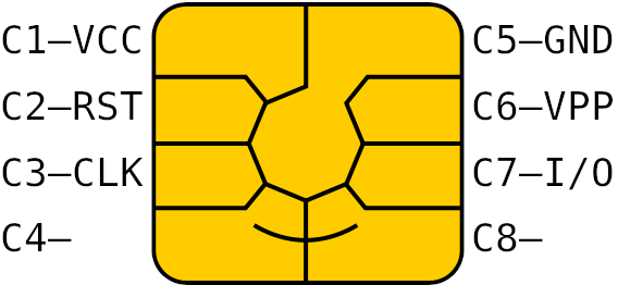
Common IC cards usually follow the ISO 7816-3 standard and have the same pinout and contact shape. Image source.
| Bus Pirate | SLE4442 | Description |
|---|---|---|
| IO0/SDA | C7 - I/O | Bidirectional data |
| IO1/SCL | C3 - CLK | Clock |
| IO2/RST | C2 - RST | Reset |
| Vout | C1 - VCC | 5volt power supply |
| GND | C5 - GND | Ground |
Connect the Bus Pirate to the smart card as shown in the table above.
Card Identification
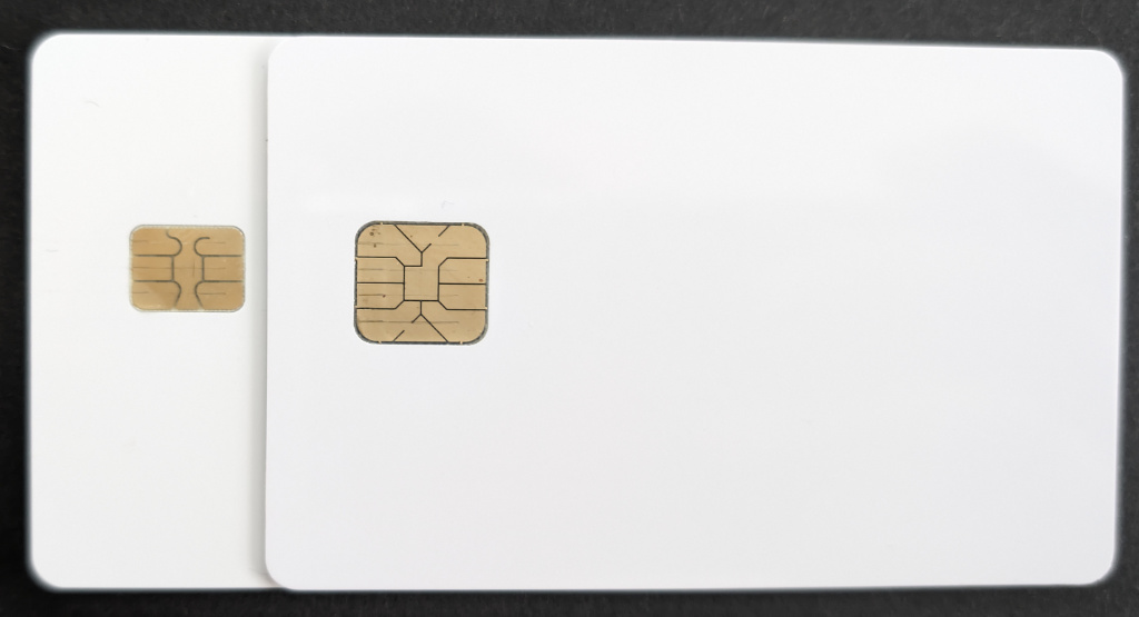
The card on the left with the smaller 6 pin contact area is a SLE4442. The card on the right with the larger 8 pin contact area is a 24C02 EEPROM card.
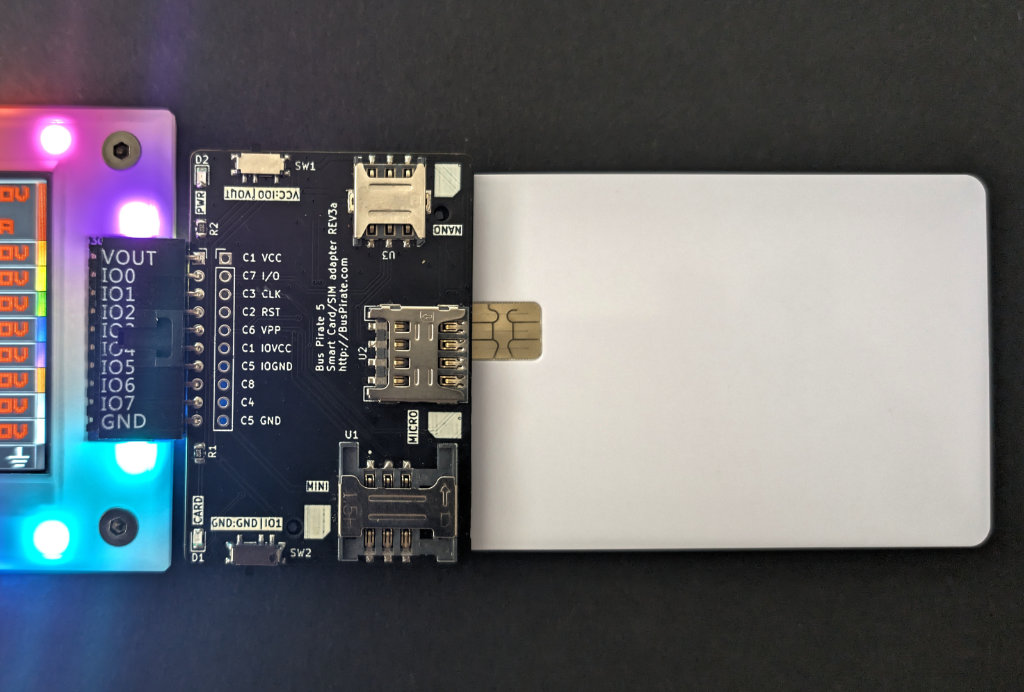
Smart IC Card and SIM card adapter
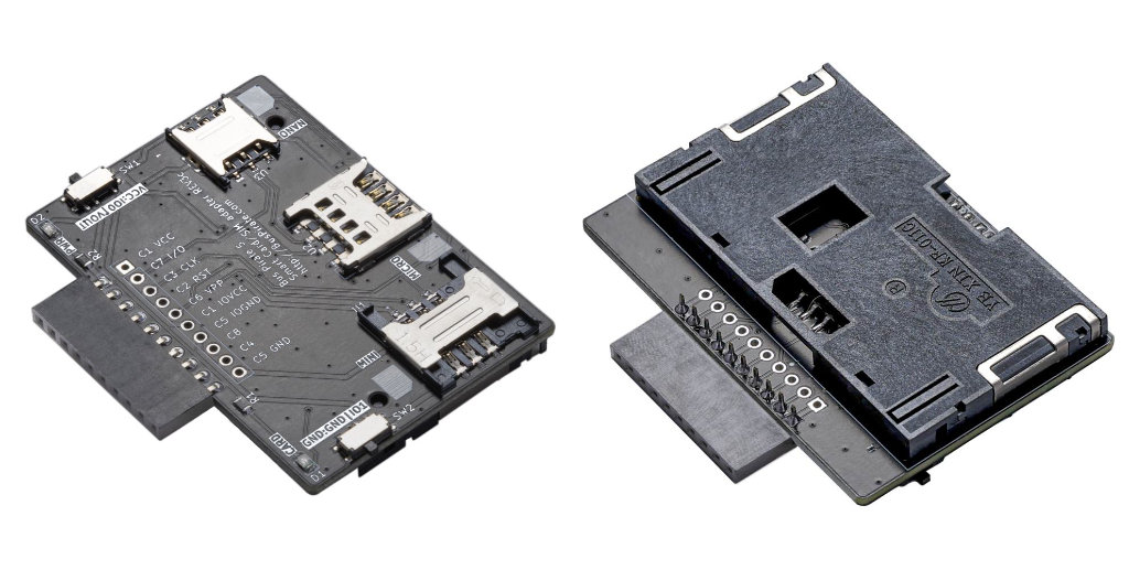
It’s possible to gently solder wires onto each pad of the chip, but a KF-011C (or similar) smart card socket is useful if you don’t want to destroy the card.
A smart IC card and SIM card adapter is available for Bus Pirate 5 with the correct connections already set. The adapter accepts most ISO 7816-3 smart cards and mini/micro/nano SIM cards.
See it in action
Setup
HiZ> m 2wire

Mode: 2WIRE
2WIRE speed
 1kHz to 1000kHz
 x. Exit
kHz (400kHz*) > 20
2WIRE>
Bus Pirate 2-WIRE mode has a bi-directional data line and a clock line, it will play well with the SLE4442. SLE4442 (clones) generally have a maximum speed of 50kHz, but some are much happier at lower speeds so let’s use 20kHz.
m 2wire- Select 2-WIRE mode.20- Configure 2-WIRE for 20kHz
2WIRE> W 5
5.00V requested, closest value: 5.00V
300.0mA requested, closest value: 300.0mA

Power supply:Enabled
Vreg output: 5.0V, Vref/Vout pin: 5.0V, Current: 2.9mA

2WIRE>
This is old tech - it needs a 5volt power supply.
W 5- Enable the onboard power supply at 5 volts
2WIRE> P
Pull-up resistors: Enabled (10K ohms @ 5.0V)

2WIRE>
The bidirectional data line is an open collector bus, the Bus Pirate and the SLE4442 can only pull the line low to 0/ground. A pull-up resistor is needed to pull the line high to 1/5volts. The Bus Pirate has built-in pull-up resistors that can be enabled with the P command.
P- Enable the onboard pull-up resistors.
Be sure to enable the pull-up resistors. The data line will never go high without them and you’ll read only 0s.
2WIRE> L
Bitorder: LSB 0b00000001
2WIRE>
SLE4442 commands and output are in the less-used Least Signification Bit (LSB) byte/word format. Enter L to set the Bus Pirate to LSB mode.
L- Set the bit order to LSB first
The SLE4442 uses Least Significant Bit first data format, but the Bus Pirate defaults to Most Significant Bit first. Be sure to set the bit order to LSB first with the L command.
Answer To Reset (ATR)
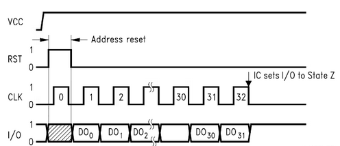
Answer To Reset (ATR) is a command sequence sent to reset and initialize the SLE4442. This diagram on page 10 of the datasheet shows the ATR sequence.
- After enabling power (VCC), the reset line (RST) low should start low.
- RST is set to high
- A single clock tick on the CLK line
- RST is set to low
- Provide 32 more clock ticks and read the 4 byte (32 bit) response on the IO line
The card returns 4 bytes that can be used to identify the card type and capabilities.
2WIRE> } { ^ }  r:4

RST LOW
RST HIGH
Tick clock: 1
RST LOW
RX: 0xA2 0x13 0x10 0x91
2WIRE>
Let’s send the ATR command via the Bus Pirate.
}- RST/reset line low to start{- RST high to begin the ATR^- One clock tick on the CLK/clock line}- RST low completes the reset sequencer:4- Read the four byte ‘answer’ to the reset sequence
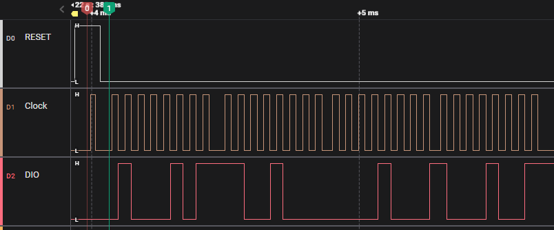
In the logic analyzer capture above, flag 0 marks after RESET is high and just before the single clock tick. RESET then goes low, and at flag 1 we clock out four bytes of data from the card on DIO.
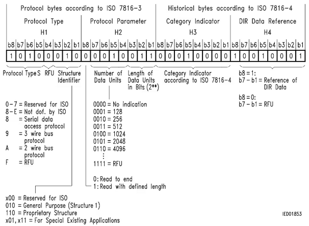
The correct reply for the SLE4442 is 0xa2 0x13 0x10 0x91. This indicates the card is an SLE44xx series card, with 256 data units of 8 bits each (256 bytes). Wikipedia has a table that explains the meaning of each field in the ATR response, or see page 25 of the datasheet.
If the response is 0x45 0xC8 0x08 0x89, then the bitorder is incorrect. The Bus Pirate is in MSB mode, but the SLE4442 uses LSB mode. Use the L command to set the Bus Pirate to LSB mode.
2WIRE> sle4442
--SLE44xx decoder--
ATR: 0xa2 0x13 0x10 0x91
Protocol Type: S 10
Structure Identifier: General Purpose (Structure 1)
Read: Read to end
Data Units: 256
Data Units Bits: 8
Security memory: 0x07 0x00 0x00 0x00
Remaining attempts: 3 (0x7)

2WIRE>
The sle4442 command automates the ATR and parses the output.
Read card memory
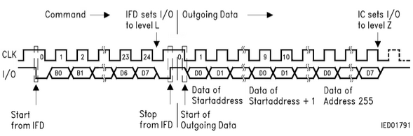
Now that the card is reset, we can interface it with a 2 wire protocol that has I2C-like START and STOP bits. Page 14 of the datasheet shows the protocol: each 3 byte command begins with a START bit and ends with a STOP bit. The Bus Pirate 2-WIRE mode sends START and STOP bits using the [/] commands.
Unlike I2C, the SLE4442 protocol does not use ACK/NACK bits.
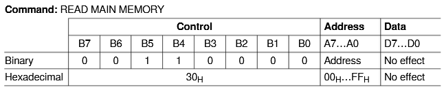
Main memory is read with the 0x30 command. The next byte is the address to start reading from (0-255), and the last byte doesn’t matter for this command. The entire 256 byte contents of the card must be read before the card will accept another command.
2WIRE> [ 0x30 0x00 0x00 ] r:256

I2C START
TX: 0x30 0x00 0x00
I2C STOP
RX: 0xA2 0x13 0x10 0x91 0xFF 0xFF 0x81 0x15
    0xFF 0xFF 0xFF 0xFF 0xFF 0xFF 0xFF 0xFF
    0xFF 0xFF 0xFF 0xFF 0xFF 0xD2 0x76 0x00
    0x00 0x04 0x00 0xFF 0xFF 0xFF 0xFF 0xFF
    0xFF 0xFF 0xFF 0xFF 0xFF 0xFF 0xFF 0xFF
...bytes removed...
    0xFF 0xFF 0xFF 0xFF 0xFF 0xFF 0xFF 0xFF

2WIRE>
Let’s put that all together. Begin the command with a START bit, then send the command, address and dummy bytes, end with a STOP bit. Finally, read all 256 bytes from the card.
[- I2C style START bit0x30- Read memory command0x00- Start reading from address 0x000x00- Dummy byte, no function in SLE4442]- I2C style STOP bitr:256- Read 256 bytes
The first 32 bytes or so include the ATR data and some other information about the card (depending on manufacturer). On a new card the rest of the memory will be 0xFF.
Unlock write access
The SLE4442 has a write protect feature that requires a 3 byte passcode to write to the card. After three incorrect passcode attempts the card is permanently locked to prevent brute force guessing of the code.
Read security memory
| Command | Control | Address | Data | Read | Remark |
|---|---|---|---|---|---|
| Read Security Memory | 31H | No effect | No effect | 4 bytes | Check Error Counter (byte 1) |
A four byte security memory area contains the remaining unlock attempts, and the three byte passcode. The three passcode bytes will always read 0x00 when the card is locked. Read the security memory using the 0x31 command.
2WIRE> [ 0x31 0x00 0x00 ] r:4

I2C START
TX: 0x31 0x00 0x00
I2C STOP
RX: 0x07 0x00 0x00 0x00
2WIRE>
The command to read the security memory is similar to the command to read the main memory, but with a different command byte. The command is:
[- I2C style START bit0x31- Read security memory command0x00- Start reading from address 0x000x00- Dummy byte, no function in SLE4442]- I2C style STOP bitr:4- Read 4 bytes
The first byte of the response (0x07) indicates the number of unlock attempts that remain. The remaining bytes are the passcode, which will always be 0x00 if the card is locked.
2WIRE> = 0x07
 =0x07 =7 =0b00000111
2WIRE>
Converting 0x07 to binary (0b111) indicates that 3 attempts remain on this card.
Send passcode
| Command | Control | Address | Data | Remark |
|---|---|---|---|---|
| Compare Verification Data | 33H | 01H-03H | Passcode bytes 1-3 | Send >256 clock ticks for processing |
| Update Security Memory | 39H | 00H | Error Counter | Write free bit in Error Counter: 0000 0ddd binary |
Unlocking the card is a multiple step process:
- Choose a remaining passcode attempt bit using the
0x39command - Write each byte of the passcode using the
0x33command - Reset the remaining passcode attempts using the
0x39command - Read the security memory again to verify the passcode was accepted
Choose a remaining passcode attempt bit
2WIRE> [ 0x39 0x00 0b110 ] ^:1000

I2C START
TX: 0x39 0x00
TX: 0b00000110
I2C STOP
Tick clock: 1000
2WIRE>
The first byte in the security memory is 0x07 (0b111). This means that three passcode attempts remain. We need to choose a ‘1’ bit to use for the next passcode attempt. If we enter the wrong passcode, this bit will be set to 0 and two attempts will remain.
[- I2C style START bit0x39- Update security memory command0x00- Security memory address to write0b110- Choose a remaining passcode attempt bit, we’re using bit 0 (0b110), but any bit with a ‘1’ will work (0b011, 0b101)]- I2C style STOP bit^:1000- Send 1000 clock ticks to complete the command
Security commands require ~256 clock ticks to complete at 50kHz. We use ^:1000 to send 1000 clock ticks to ensure the command is completed at our lower speed of 20kHz.
Write passcode bytes
2WIRE> [0x33 0x01 0xff] ^:1000

I2C START
TX: 0x33 0x01 0xFF
I2C STOP
Tick clock: 1000
2WIRE> [0x33 0x02 0xff] ^:1000

I2C START
TX: 0x33 0x02 0xFF
I2C STOP
Tick clock: 1000
2WIRE> [0x33 0x03 0xff] ^:1000

I2C START
TX: 0x33 0x03 0xFF
I2C STOP
Tick clock: 1000
2WIRE>
The passcode is written to the security memory in three steps. Each byte is written with the 0x33 command to addresses 0x01, 0x02, and 0x03. The default passcode is generally 0xff 0xff 0xff for new SLE4442 cards.
[0x33 0x01 0xff] ^:1000- Write 0xff to security memory address 0x01[0x33 0x02 0xff] ^:1000- Write 0xff to security memory address 0x02[0x33 0x03 0xff] ^:1000- Write 0xff to security memory address 0x03
The default passcode is generally 0xff 0xff 0xff for new SLE4442 cards.
Reset passcode attempts
2WIRE> [0x39 0x00 0xff] ^:1000

I2C START
TX: 0x39 0x00 0xFF
I2C STOP
Tick clock: 1000
2WIRE>
The remaining passcode attempts are reset to 0x07 (0b111) after the passcode is accepted. This is done with the 0x39 command to address 0x00 with the data 0xff.
[0x39 0x00 0xff] ^:1000- Reset the remaining passcode attempts to 0x07
Verify card is unlocked
2WIRE> [0x31 0x00 0x00] r:4

I2C START
TX: 0x31 0x00 0x00
I2C STOP
RX: 0x07 0xFF 0xFF 0xFF
2WIRE>
If the card was successfully unlocked, the remaining passcode attempts will be reset to 0x07 (0b111). We can verify this by reading the security memory again.
[0x31 0x00 0x00] r:4- Read the security memory
The remaining passcode attempts are 0x07 (0b111), meaning the card is unlocked. We can now see that the passcode bytes are 0xff 0xff 0xff.
If the passcode was incorrect, the passcode attempt bit will be set to 0 and two attempts will remain. Use a different bit for the next passcode attempt - we used 0b110 (bit 0) for the first attempt, so we could use 0b101 (bit 1) for the next attempt.
Write card memory
| Command | Control | Address | Data |
|---|---|---|---|
| UPDATE MAIN MEMORY | B7…B0 | A7…A0 | D7…D0 |
| Hexadecimal | 38H | 00H…FFH | Input data |
The SLE4442 has 256 bytes of memory that can be written with the 0x38 command. Only one byte of data can be written per command at the location indicated by the address byte.
It’s best to avoid writing to the first 32 bytes of memory, as this area contains the ATR data and other information about the card. Overwriting the ATR data can cause the card to stop working.
2WIRE> [0x38 255 0x55 ] ^:1000

I2C START
TX: 0x38
TX: 255
TX: 0x55
I2C STOP
Tick clock: 1000
2WIRE>
Let’s write 0x55 to address 255 (0xff) in the main memory.
[- I2C style START bit0x38- Write memory command255- Write at address 255 (0xff)0x55- Write 0x55 to address 255]- I2C style STOP bit^:1000- Send 1000 clock ticks to complete the command
Card must be unlocked or writes will fail.
2WIRE> [0x30 0 0] r:256

I2C START
TX: 0x30
TX: 0 0
I2C STOP
RX: 0xA2 0x13 0x10 0x91 0xFF 0xFF 0x81 0x15
...lines removed...
    0xFF 0xFF 0xFF 0xFF 0xFF 0xFF 0xFF 0x55

2WIRE>
Now, let’s verify that the data was written correctly by reading the memory again.
[0x30 0 0] r:256- Read 256 bytes
The last byte of the memory is now 0x55, the write was successful.
Change passcode
| Command | Control | Address | Data |
|---|---|---|---|
| UPDATE SECURITY MEMORY | B7…B0 | A7…A0 | D7…D0 |
| Hexadecimal | 39H | 00H…03H | Input data |
For our final act, let’s update the passcode so intrepid hackers can’t break in using the default.
The new passcode is written to the security memory in three steps. Each byte is written with the 0x39 command to addresses 0x01, 0x02, and 0x03.
2WIRE> [0x39 0x01 0x12] ^:1000

I2C START
TX: 0x39 0x01 0x12
I2C STOP
Tick clock: 1000
2WIRE> [0x39 0x02 0x34] ^:1000

I2C START
TX: 0x39 0x02 0x34
I2C STOP
Tick clock: 1000
2WIRE> [0x39 0x03 0x56] ^:1000

I2C START
TX: 0x39 0x03 0x56
I2C STOP
Tick clock: 1000
2WIRE>
Let’s set the passcode to 0x12 0x34 0x56.
[0x39 0x01 0x12] ^:1000- Write 0x12 to security memory address 0x01[0x39 0x02 0x34] ^:1000- Write 0x34 to security memory address 0x02[0x39 0x03 0x56] ^:1000- Write 0x56 to security memory address 0x03
Verify passcode update
2WIRE> [0x31 0x00 0x00] r:4

I2C START
TX: 0x31 0x00 0x00
I2C STOP
RX: 0x07 0x12 0x34 0x56
2WIRE>
The passcode is now 0x12 0x34 0x56. Let’s verify the passcode was updated by reading the security memory again.
[0x31 0x00 0x00] r:4- Read the security memory
Three passcode attempts remain (0x07), and the passcode is now 0x12 0x34 0x56.
Variants
SLE4428 is similar to the SLE4442, but with a few notable differences. SLE4428 is a 1024 byte EEPROM card, and it does not have the passcode write protection feature of the SLE4442. If you’re looking for a bigger card for a new project, check out 24Cxx EEPROM cards. 24Cxx cards come in larger sizes up to 64K, and have a standard I2C interface.
If you can’t help but deal with an SLE4428 card, it should work similar to the SLE4442 with a 2 byte address field.
sle4442 command
The sle4442 command in the Bus Pirate 2-WIRE mode automates the process of reading, writing and unlocking a SLE4442 smart card.
2WIRE> sle4442 init
--SLE44xx decoder--
ATR: 0xa2 0x13 0x10 0x91
Protocol Type: S 10
Structure Identifier: General Purpose (Structure 1)
Read: Read to end
Data Units: 256
Data Units Bits: 8
Security memory: 0x07 0x00 0x00 0x00
Remaining attempts: 3 (0x7)
Perform Answer To Reset (ATR) and decode the response.
2WIRE> sle4442 dump
--SLE44xx decoder--
ATR: 0xa2 0x13 0x10 0x91
Protocol Type: S 10
Structure Identifier: General Purpose (Structure 1)
Read: Read to end
Data Units: 256
Data Units Bits: 8
Security memory: 0x07 0x00 0x00 0x00
Remaining attempts: 3 (0x7)
Protection memory: 0xff 0xff 0xff 0xff
Memory:
0xa2 0x13 0x10 0x91 0xff 0xff 0x81 0x15 0xff 0xff 0xff 0xff 0xff 0xff 0xff 0xff 0xff 0xff 0xff 0xff 0xff 0xd2 0x76 0x00 0x00 0x04 0x00 0xff 0xff 0xff 0xff 0xff 0xff 0xff 0xff 0xff 0xff 0xff 0xff 0xff 0xff 0xff 0xff 0xff 0xff 0xff 0xff 0xff 0xff 0xff 0xff 0xff 0xff 0xff 0xff 0xff 0xff 0xff 0xff 0xff 0xff 0xff 0xff 0xff 0xff 0xff 0xff 0xff 0xff 0xff 0xff 0xff 0xff 0xff 0xff 0xff 0xff 0xff 0xff 0xff 0xff 0xff 0xff 0xff 0xff 0xff 0xff 0xff 0xff 0xff 0xff 0xff 0xff 0xff 0xff 0xff 0xff 0xff 0xff 0xff 0xff 0xff 0xff 0xff 0xff 0xff 0xff 0xff 0xff 0xff 0xff 0xff 0xff 0xff 0xff 0xff 0xff 0xff 0xff 0xff 0xff 0xff 0xff 0xff 0xff 0xff 0xff 0xff 0xff 0xff 0xff 0xff 0xff 0xff 0xff 0xff 0xff 0xff 0xff 0xff 0xff 0xff 0xff 0xff 0xff 0xff 0xff 0xff 0xff 0xff 0xff 0xff 0xff 0xff 0xff 0xff 0xff 0xff 0xff 0xff 0xff 0xff 0xff 0xff 0xff 0xff 0xff 0xff 0xff 0xff 0xff 0xff 0xff 0xff 0xff 0xff 0xff 0xff 0xff 0xff 0xff 0xff 0xff 0xff 0xff 0xff 0xff 0xff 0xff 0xff 0xff 0xff 0xff 0xff 0xff 0xff 0xff 0xff 0xff 0xff 0xff 0xff 0xff 0xff 0xff 0xff 0xff 0xff 0xff 0xff 0xff 0xff 0xff 0xff 0xff 0xff 0xff 0xff 0xff 0xff 0xff 0xff 0xff 0xff 0xff 0xff 0xff 0xff 0xff 0xff 0xff 0xff 0xff 0xff 0xff 0xff 0xff 0xff 0xff 0xff 0xff 0xff 0xff 0xff 0xff 0xff 0xff 0xff 0xff 0xff 0xff 0xff 0xff 0xff 0xff 0xff
Read the card memory, and more. See the 2-Wire mode documentation for more information.
2WIRE> sle4442 -h
usage:
sle4442 [init|dump|unlock|write|erase|psc]
	[-a <address>] [-v <value>] [-p <current psc>] [-n <new psc>] [-f <dump file>] [-h(elp)]
Initialize and probe: sle4442 init
Dump contents: sle4442 dump
Unlock card: sle4442 unlock -p 0xffffff
Write a value: sle4442 write -a 0xff -v 0x55
Erase memory: sle4442 erase
Update PSC: sle4442 psc -p 0xffffff -n 0x000000
Dump contents to file: sle4442 dump -f dump.bin
Dump format: DATA[0:255],SECMEM[256:259],PRTMEM[260:263]

SLE4442 smart card interface
init	Initialize card with ISO7816-3 ATR. Default action
dump	Display main, security and protect memory
unlock	Unlock card with Programmable Security Code (PSC)
write	Write data to card (requires unlock)
erase	Erase data from range 0x32-0x255 (requires unlock)
psc	Change Programmable Security Code (PSC)
-a	Write address flag
-v	Write value flag
-p	Current Programmable Security Code (PSC) flag
-n	New Programmable Security Code (PSC) flag
-f	Dump file name flag

2WIRE>
Use sle4442 -h to see the latest options and features.
Get a Bus Pirate
Get Bus Pirate & Accessories
- Browse Complete Bus Pirate hardware collection
- Bus Pirate 5 REV10 with enclosure
- Probe Cable Kit
- Auxiliary Cable Kit
- Quick Connect Adapter