SI7021, HTU21, SHT21 Humidity & Temperature I2C
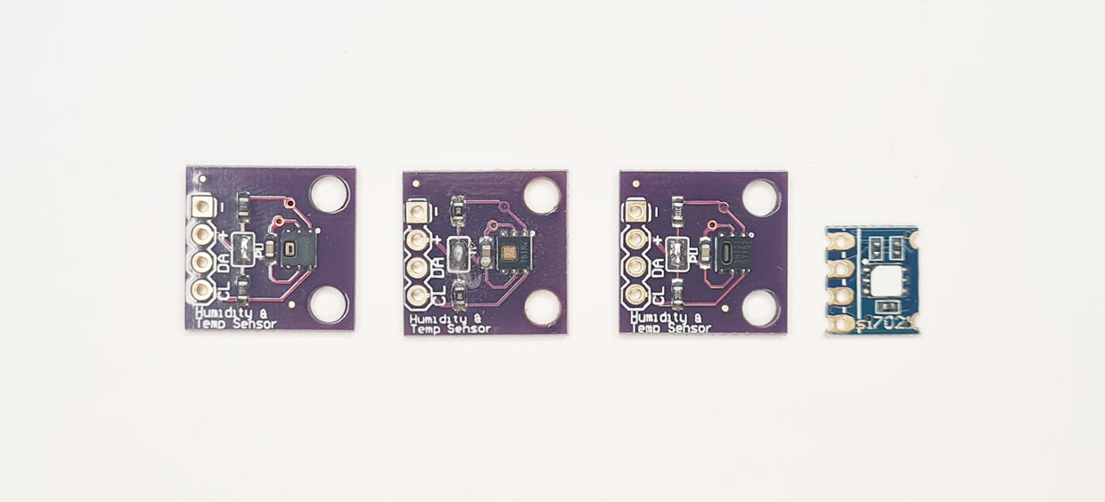
SI7021, HTU21 and SHT21 are nearly identical I2C temperature (-10 to 85C) and humidity (0-80%) sensors. They’re super simple to use over the common and friendly I2C bus.
Get Bus Pirate & Accessories
Connections
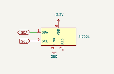
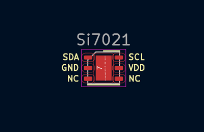
| Bus Pirate | SHT21 | Description |
|---|---|---|
| SDA | SDA | I2C Data |
| SCL | SCL | I2C Clock |
| Vout/Vref | VDD | 3.3volt power supply |
| GND | GND | Ground |
See it in action
Setup
HiZ> m i2c

Mode: I2C
I2C speed
 1kHz to 1000kHz
 x. Exit
kHz (400kHz*) > 400
Clock stretching
 1. OFF*
 2. ON
 x. Exit
OFF (1) > 1
I2C>
SI7021 is an I2C device, so we need to set the Bus Pirate to I2C mode.
m i2c- set the Bus Pirate to I2C mode, or just hitmto select from the menu.400- set the I2C bus speed to 400kHz.1- disable clock stretching.
The SI7021 supports clock stretching, which is a way for the device to signal that it needs more time to process a command. It adds some complexity though, so we’ve disabled it for this demo.
Power supply
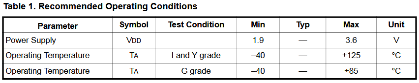
According to the datasheet, the SI7021 requires a 1.9-3.6 volt power supply.
Image source: datasheet.
I2C> W 3.3
3.30V requested, closest value: 3.30V
300.0mA requested, closest value: 300.0mA

Power supply:Enabled
Vreg output: 3.3V, Vref/Vout pin: 3.3V, Current: 2.6mA

I2C>
Let’s set the Bus Pirate to power the chip at 3.3volts, a very common voltage for modern I2C devices.
W 3.3- enable the onboard power supply at 3.3volts.
Pull-up resistors
I2C> P
Pull-up resistors: Enabled (10K ohms @ 3.3V)

I2C>
I2C is an open collector output bus, the Bus Pirate and the SI7021 can only pull the line low to 0 (ground). A pull-up resistor is needed to pull the line high to 1 (3.3 volts). The Bus Pirate has built-in pull-up resistors that can be enabled with the P command.
P- Enable the onboard pull-up resistors.
Be sure to enable the pull-up resistors. Without them, the clock data line will never go high and you’ll read only 0s.
I2C address scan
I2C> scan
I2C address search:
0x00 (0x00 W)
0x40 (0x80 W) (0x81 R)

Found 3 addresses, 1 W/R pairs.

I2C>
We need the correct I2C address to talk to the sensor. We could look in the datasheet, or we can run the handy I2C address scanner.
scan- Scan the I2C bus for devices
The scanner found an I2C device at address 0x40 (0x80 write, 0x81 read).
If the scanner doesn’t find the device, ensure the power supply is enabled W 3.3 and the pull-up resistors are enabled P.
Commands
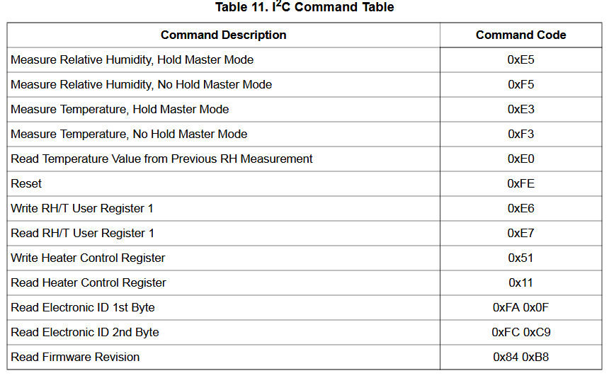
The SI7021 has a number of commands that can be sent over the I2C bus. In this demo we’ll use the following commands:
0xf5- Measure humidity, no hold master0xf3- Measure temperature, no hold master0xe0- Read temperature from previous humidity measurement0xe6- Write user (configuration) register 10xe7- Read user (configuration) register 1
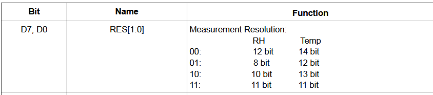
Measurement resolution
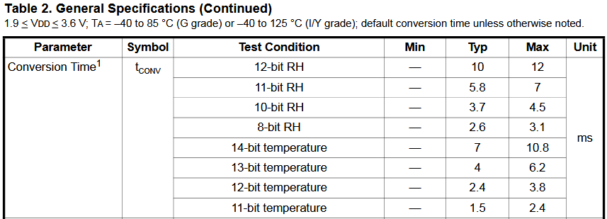
Accurate temperature and humidity measurements take longer than low resolution measurements. The table shows that an 8-bit humidity measurement completes in 3.1ms, while a 12-bit resolution measurement takes four times longer (12ms).
Each humidity measurement also triggers a temperature measurement which is used for compensation. The total measurement time is humidity (12ms @ 12-bits) + temperature (10.8ms @ 14-bits) = 22.8ms (~23ms).
If you want the highest resolution and you have the time to spare, SI7021 can do that! In a hurry and don’t need the absolute best accuracy? SI7021 can do that too! The next steps configure the measurement resolution, or you can skip straight to measuring temperature and humidity.
User register 1
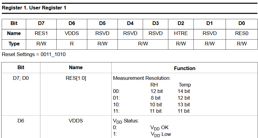
User register 1 is a strange name for the SI7021 configuration register. The settings in this register control the measurement resolution and heater.
- Bit 7 and bit 0 of the user register set the measurement resolution.
- Bit 6 shows the power status.
- Bit 2 controls a heater in the sensor. The heater is used to test the sensor, dry condensation or take dew-point measurements.
- The other bits are reserved (RSVD) and should not be changed from the default values.
Read user register 1
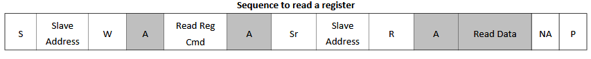
Reading user register 1 is a two step process. First write the read register command to the SI7021 write address, then read the result from the read address.
- S - Begin with an I2C START bit
- SA + W - Send the SI7021 write address (0x80)
- Read Reg Cmd - Send the read user register command (0xe7)
- Sr - Send an I2C repeated START bit
- SA + R - Send the SI7021 read address (0x81)
- Read Data - Read one byte of data from the user register
- P - End with an I2C STOP bit
A and NA in the datasheet diagram above refer to acknowledge and not acknowledge bits. The Bus Pirate automatically sends an ACK after each byte, except the last byte which is NACKed.
I2C> [0x80 0xe7[0x81 r]

I2C START
TX: 0x80 ACK 0xE7 ACK
I2C REPEATED START
TX: 0x81 ACK
RX: 0x3A NACK
I2C STOP
I2C>
SI7021 should default to 12-bit humidity and 14-bit temperature measurement after power up. Let’s read the configuration from user register 1 to be sure.
[- I2C START bit0x80- SI7021 write address0xe7- Read user register command[- I2C repeated START bit0x81- SI7021 read addressr- Read one byte]- I2C STOP bit
User register 1 returns 0x3A. Let’s convert the register value to binary so it’s a bit easier to read.
Decode user register 1
I2C> = 0x3a
 =0x3A =58 =0b00111010= ':'
I2C>
The = convert command displays a value in HEX, decimal, binary and ASCII formats. The SI7021 user register 1 value 0x3A converts to 0b00111010 in binary.
0b
00111010
Looking at the user register layout again, bits 7 and 0 select the measurement resolution. Bit 7 and 0 are both 0, which means the SI7021 is set to 12-bit resolution for humidity and 14-bit resolution for temperature.
Write user register 1
This demo uses the default 12-bit humidity and 14-bit temperature resolution, so there is no need to change the configuration. Let’s look at how to change it if you’d like to use a different resolution or the setting is incorrect.

Writing user register 1 is over I2C is similar to reading it.
- S - Begin with an I2C START bit
- SA + W - Send the SI7021 write address (0x80)
- Write Reg Cmd - Send the write user register command (0xe6)
- Data - Send the new user register value (0x3A for 12-bit humidity and 14-bit temperature)
- P - End with an I2C STOP bit
It is important to only change the bits that control the measurement resolution (bits 7 and 0). The reserved bit should not be changed from the default values.
- 0b
00111010- bit 7 and 0 are00, 12bit RH, 14bit Temp - 0b
00111011- bit 7 and 0 are01, 8bit RH, 12bit Temp - 0b
10111010- bit 7 and 0 are10, 10bit RH, 13bit Temp - 0b
10111011- bit 7 and 0 are11, 11bit RH, 11bit Temp
These are the register values for each of the four measurement options, with the reserved bits set to the default values.
I2C> [0x80 0xe6 0b00111010]

I2C START
TX: 0x80 ACK 0xE6 ACK
TX: 0b00111010 ACK
I2C STOP
I2C>
Let’s configure user register 1 for 12-bit humidity and 14-bit temperature measurements.
[- I2C START bit0x80- SI7021 write address0xe6- Write user register command0b00111010- Write the user register value (0x3A) for 12-bit humidity and 14-bit temperature]- I2C STOP bit
Go back and read the user register again to confirm the value was written correctly if you’d like, or keep going to finally actually measure temperature and humidity!
Measure humidity
SI7021 has two types of measurement commands.
- I2C clock stretching pauses the master (Bus Pirate) by holding the clock line low until the measurement is complete.
- No Hold Master Mode commands, on the other hand, cause the SI7021 to ignore its I2C read address until the measurement is complete.
Clock stretching is useful, but it ties up the I2C bus while the measurement is in progress and no other sensors can be read until it completes. Let’s use the no hold master commands with a delay instead.
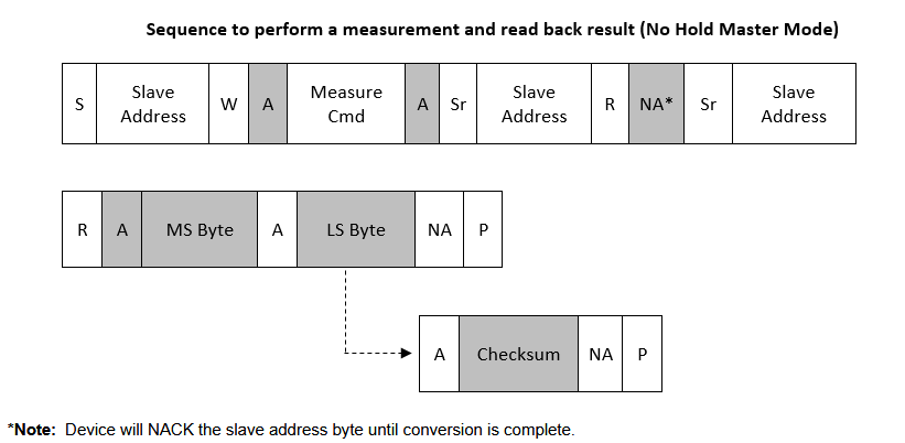
Triggering a humidity measurement follows the typical I2C transaction pattern: write the command to the write address, then read the result from the read address. The only trick is that we need to add the correct delay before reading the result. If we try to read before the measurement is complete, the SI7021 will not acknowledge (NACK) the read address.
- S - Begin with an I2C START bit
- SA + W - Send the SI7021 write address (0x80)
- Measure Humidity Cmd - Send the measure humidity command, no hold measurement mode (0xf5)
- Sr - Send an I2C repeated START bit (or we could send a STOP bit and a new START bit before reading)
- SA+R, NA - The SI7021 will not ACK its read address until the measurement is complete, so we need to wait a bit before reading the result.
- SA + R - Send the SI7021 read address (0x81)
- MS/LS bytes - Read the two byte humidity measurement, and an optional checksum byte.
- P - End with an I2C STOP bit
I2C> [0x80 0xf5] D:23 [0x81 r:2]

I2C START
TX: 0x80 ACK 0xF5 ACK
I2C STOP
Delay: 23ms
I2C START
TX: 0x81 ACK
RX: 0xAA ACK 0x02 NACK
I2C STOP
We’re going to deviate from the datasheet example a bit here. Instead of repeating the read address until the measurement is complete, we’ll end the write command with an I2C STOP bit, then wait for a fixed delay of 23ms before reading the result.
[- I2C START bit0x80- SI7021 write address0xf5- Measure humidity command, no hold master mode]- I2C STOP bit, ends this transactionD:23- Delay for 23ms to allow the measurement to complete[- I2C START bit, begins the read transaction0x81- SI7021 read addressr:2- Read two bytes of data (the humidity measurement)]- I2C STOP bit, ends the read transaction
The two byte humidity measurement is 0xaa and 0x02. The first byte is the most significant byte (MSB) and the second byte is the least significant byte (LSB).
23ms is the maximum time it takes to complete a 12-bit humidity (12ms) and 14-bit temperature (10.8ms) measurement.
Convert to humidity
I2C> = 0xaa02
 =0xAA02.16 =43522.16 =0b1010101000000010.16
I2C>
Let’s convert the HEX bytes into a decimal number for easier calculations.
= 0xaa02- find the decimal equivalent of 0xaa02 (43522).
$$\text{RH} = \left(\frac{125 \times \text{value}}{65536}\right) - 6$$ $$\text{RH} = \left(\frac{125 \times 43522}{65536}\right) - 6$$ $$\text{RH} = 77.01%$$
Now we can calculate humidity using the formula above. The humidity is 77% here in the office, what did you get?
Measure temperature
We could use the Measure Temperature, No Hold Master command (0xf3) to trigger a new temperature measurement, which will include an additional 10.8ms delay.
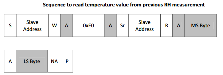
However, each humidity measurement also triggers a temperature measurement. The Read Temperature from Previous Humidity Measurement command (0xe0) reads the temperature from the last humidity measurement.
- S - Begin with an I2C START bit
- SA + W - Send the SI7021 write address (0x80)
0xe0- Send the read temperature from previous humidity measurement command- Sr - Send an I2C repeated START bit
- SA + R - Send the SI7021 read address (0x81)
- MS/LS bytes - Read the two byte temperature measurement
- P - End with an I2C STOP bit
I2C> [0x80 0xe0 [ 0x81 r:2]

I2C START
TX: 0x80 ACK 0xE0 ACK
I2C START
TX: 0x81 ACK
RX: 0x5E ACK 0xD4 NACK
I2C STOP
Let’s read the temperature from the last humidity measurement.
[- I2C START bit0x80- SI7021 write address0xe0- Read temperature from previous humidity measurement command[- I2C repeated START bit0x81- SI7021 read addressr:2- Read two bytes of data (the temperature measurement)]- I2C STOP bit
Convert to temperature
I2C> = 0x5ed4
 =0x5ED4.16 =24276.16 =0b0101111011010100.16
I2C>
Convert the HEX bytes into a decimal number with the = convert command.
= 0x5ed4- find the decimal equivalent of 0x5ed4 (24276).
$$\text{Temp C} = \left(\frac{175.72 \times \text{value}}{65536}\right) - 46.85$$ $$\text{Temp C} = \left(\frac{175.72 \times 24276}{65536}\right) - 46.85$$ $$\text{Temp C} = 18.24C$$
Now we can calculate the temperature using the formula above. The temperature is 18.24C.
si7021 command
I2C> si7021
Read temperature and humidity from SI7021/HTU21/SHT21 sensor
Humidity: 71.05% (0x9d 0xca)
Temperature: 18.79C (0x5f 0xa0)
Serial Number: 0xffff0000000015ff

I2C>
si7021 command reads the SI7021, HTU21, SHT21 or HDC1080 temperature and humidity sensor. It returns the humidity, temperature and serial number in a single command.
Get a Bus Pirate
Get Bus Pirate & Accessories
- Browse Complete Bus Pirate hardware collection
- Bus Pirate 5 REV10 with enclosure
- Probe Cable Kit
- Auxiliary Cable Kit
- Quick Connect Adapter