JTAG & SWD Pin Finder JTAG
blueTag is an open source JTAG and SWD pin finder integrated into the Bus Pirate firmware. It can identify the JTAG/SWD pins on a target device by sending a series of test signals and analyzing the responses.
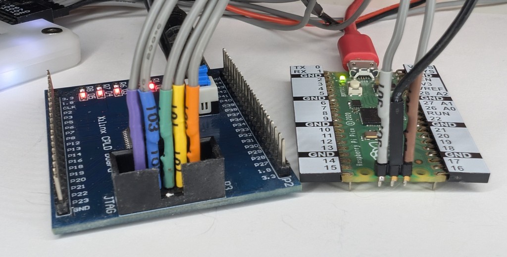
In this demo we’ll scan two target devices:
- A Xilinx CPLD development board from AliExpress with no documentation.
- A Raspberry Pi PICO board
We connected both boards at the same time to different Bus Pirate IO pins. blueTag is able to identify both.
See it in action
Connections
- Connect the Bus Pirate IO pins to the suspected JTAG/SWD pins on the target device.
- Start with IO0 and work your way up to IO7.
- If possible, look for ground pours and power pins on the JTAG or SWD port and avoid connecting IO pins to them.
- Connect the Bus Pirate ground pin to the target device ground.
- Power the device.
Start with IO0 and work your way up to IO7. Each channel added increases the search time.
This demo assumes the target device has its own power supply.
Try to avoid connecting IO pins to ground or power pins on the JTAG or SWD port. Look for large shared ground pours (copper regions) on the top and bottom of the PCB, avoid pins connected to them.
Setup
HiZ> m jtag

Mode: JTAG
JTAG> W 3.3
3.30V requested, closest value: 3.30V
300.0mA requested, closest value: 300.0mA

Power supply:Enabled
Vreg output: 3.3V, Vref/Vout pin: 3.3V, Current: 3.0mA

JTAG>
JTAG mode hosts the blueTag command. Enter JTAG mode with the m command and enable an appropriate power supply with the W command.
m jtag- set the Bus Pirate to JTAG mode.W <voltage>- enable an appropriate power supply to probe the target device JTAG/SWD pins.
Both the Xilinx CPLD dev board and the RP2040 PICO board we’re probing are 3.3volt devices. We set the power supply to 3.3volts for this demo, but your target device may require a different voltage.
Measure the target device supply/pin voltage. The Bus Pirate IO pin voltage should be set to match with the W power supply command.
If the target has an obvious voltage out pin, then you can power the Bus Pirate IO pins from that. Attach the Bus Pirate VOUT pin to the target voltage out pin and skip the W power supply command setup step.
Search for JTAG pins
JTAG> bluetag jtag -c 8
Number of channels set to: 8

     Progress: [##########################] 100.00%

     [  Pinout  ]  TDI=IO0 TDO=IO3 TCK=IO4 TMS=IO2 TRST=N/A

     [ Device 0 ]  0x59602093 (mfg: 'Xilinx', part: 0x9602, ver: 0x5)

JTAG>
bluetag jtag -c <channels>- search for JTAG pins on the target device. The-cflag specifies the number of channels to search, starting from IO0.
Search for JTAG pins on the target device. The CPLD board is identified as a Xilinx device with the pinout: TDI=IO0 TDO=IO3 TCK=IO4 TMS=IO2 TRST=N/A.
If the scan fails, you can try again with the -d flag to disable pin pulsing. This may help find stubborn JTAG pins.
Search for SWD pins
JTAG> bluetag swd -c 8
Number of channels set to: 8

     Progress: [##########################] 100.00%

     [  Pinout  ]  SWDIO=IO5 SWCLK=IO6

     [ Device 0 ]  0x0BC12477 (mfg: 'ARM Ltd', part: 0xbc12, ver: 0x0)

JTAG>
bluetag swd -c <channels>- search for SWD pins on the target device. The-cflag specifies the number of channels to search, starting from IO0.
Search for SWD pins on the target device. The PICO board is identified as an ARM device with the pinout: SWDIO=IO5 SWCLK=IO6.
The Bus Pirate can find its own SWD pins. Connect IO0-IO2 to the three debug pins on the bottom of the Bus Pirate and then run bluetag swd -c 3.