AT24C256 EEPROM I2C
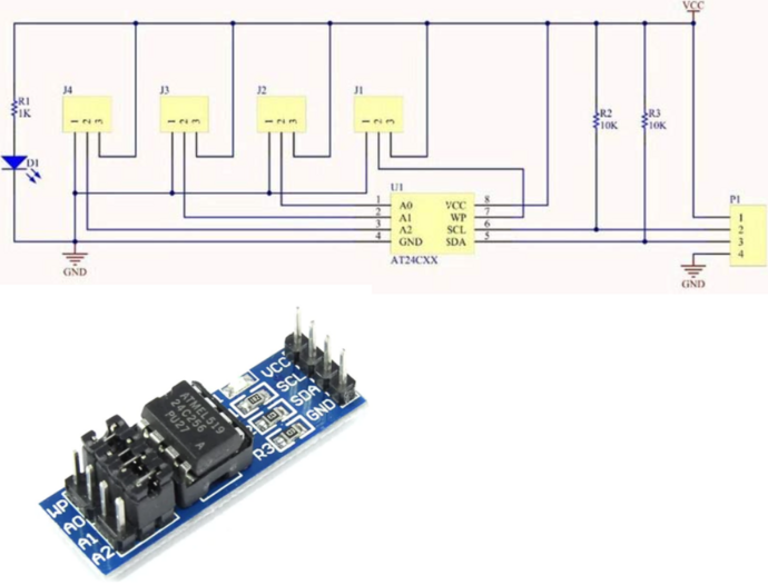
The infamous cheap AT24C256 I2C EEPROM breakout board provides 32K bytes of storage for your projects.
- Cost: ~$2
- Size: 32768 bytes
- VCC: 2.7 - 5.5V
- It includes I2C pull-ups
- Speeds: 1 MHz (5V), 400 kHz (2.7V, 2.5V)
- 64-byte Page Write Mode (Partial Page Writes Allowed).
- I2C address ranges from 0x50 to 0x57 and can be configured using the A jumpers (A0-A2)
AT24C256 is a widely used and widely cloned EEPROM chip. Cheap boards from your favorite online store may use clones with slightly different features. The good news is the clones usually have upgraded features, but the basic way of reading and writing data remains the same.
Get Bus Pirate & Accessories
Connections
| Bus Pirate | AT24C256 board | Description |
|---|---|---|
| SDA | SDA | I2C Data |
| SCL | SCL | I2C Clock |
| Vout/Vref | VCC | 5volt power supply |
| GND | GND | Ground |
See it in action
Setup
Considering:
- AT24C256’s datasheet max speed
- AT24C256 board pull-ups are 10k
- You’ve purchased a low-quality clone from AliExpress or any other source
- The length of the Bus pirate cable
We’re going to be very conservative and operate at:
- 5V, 100kHz.
- Max current: 50ma.
HiZ> m i2c

Mode: I2C
I2C speed
 1kHz to 1000kHz
 x. Exit
kHz (400kHz*) > 100
Clock stretching
 1. OFF*
 2. ON
 x. Exit
OFF (1) > 1
I2C>
- Use the
mmode command and select I2C - Configure I2C for 100kHz and 8bits of data
Power supply
I2C> W 5 50
5.00V requested, closest value: 5.00V
50.0mA requested, closest value: 50.0mA

Power supply:Enabled
Vreg output: 4.9V, Vref/Vout pin: 4.9V, Current: 10.9mA

I2C>
- Enable the onboard power supply with the
Wcommand, and configure it for 5volts output. - Select a current limit of at least 50mA.
Pull-up resistors
I2C> P
Pull-up resistors: Enabled (10K ohms @ 4.9V)

I2C>
Since this AT24C256 board already includes pull-ups, there’s no need to utilize the pull-ups from the Bus Pirate. But we going to show how to enable them anyway.
I2C is an open collector output bus, the Bus Pirate and the at24c256 can only pull the line low to 0 (ground). A pull-up resistor is needed to pull the line high to 1 (5 volts). The Bus Pirate has built-in pull-up resistors that can be enabled with the P command.
P- Enable the onboard pull-up resistors.
I2C address scan
I2C> scan
I2C address search:
0x50 (0xA0 W) (0xA1 R)
0x58 (0xB0 W) (0xB1 R)

Found 4 addresses, 2 W/R pairs.

I2C>
Let’s see if we can find the card I2C address. We could look in the datasheet, or we can be lazy and run an I2C address scan.
scan- Scan the I2C bus for devices
This AT24C256 EEPROM is a non-original variant and includes an additional address: 0x58 (0xB0/B1). This extra address can be utilized to store data, such as a serial number. While this feature is not supported in the official AT24C256 chip, it is commonly found in certain “AT24C256 boards” sold on platforms like AliExpress.
Just use the 0x50 (0xA0/A1) address for reading and writing data to the EEPROM and ignore the 0x58 (0xB0/B1) address.
Write three bytes
I2C> [0xa0 0x00 0x69 0x41 0x42 0x43]

I2C START
TX: 0xA0 ACK 0x00 ACK 0x69 ACK 0x41 ACK 0x42 ACK 0x43 ACK
I2C STOP
I2C>
We’ll write three bytes - ‘A’(0x41), ‘B’(0x42), ‘C’(0x43) - to the EEPROM at memory location 0x69, 0x6A, and 0x6B. The AT24C256 supports partial page writes, so we can write to the EEPROM without needing to write a full 64-byte page.
[- Begin with an I2C START0xA0- is the I2C device write address: 0xA0 (the AT24C256 has a 7-bit address, so the Bus Pirate uses the 8-bit address 0xA0 for writing).0x00 0x69- is the memory address where we intend to write: 0x69. The AT24C256 has a 16bit/2byte address range.0x41 0x42 0x43- are the three data bytes we want to write.]- End with an I2C STOP
After initiating a data write to the EEPROM, you must wait up to 5ms to ensure that the write cycle is complete before starting another. If you enter the write and read commands on separate lines there will be plenty of delay for the write to complete, but if you enter it on a single line be sure to add a 5ms delay between the commands with D:5.
Read three bytes
I2C> [0xa0 0x00 0x69]

I2C START
TX: 0xA0 ACK 0x00 ACK 0x69 ACK
I2C STOP
I2C>
We’ll read three bytes from the EEPROM at memory location 0x69, 0x6A, and 0x6B. To achieve this, two commands are necessary. First, use a write command with no data to indicate the memory address we want to read.
[- Begin with an I2C START0xA0- is the I2C device write address: 0xA0 (the AT24C256 has a 7-bit address, so the Bus Pirate uses the 8-bit address 0xA0 for writing).0x00 0x69- is the 16bit/2byte memory address to read: 0x69.]- End with an I2C STOP
I2C> [0xa1 r:3]

I2C START
TX: 0xA1 ACK
RX: 0x41 ACK 0x42 ACK 0x43 NACK
I2C STOP
I2C>
Second, use the I2C read address to read the bytes from that memory location.
[- Begin with an I2C START0xA1- is the I2C device read address to access data at the location we set with the previous command: 0xA1 (the AT24C256 has a 7-bit address, so the Bus Pirate uses the 8-bit address 0xA1 for reading).r:3- reads back three bytes of data. Bytes read: 0x41 0x42 0x43 (‘A’, ‘B’, ‘C’). Each byte is separated by a space and is located at the memory addresses 0x69, 0x6A, and 0x6B respectively.]- End with an I2C STOP
If the writing process fails, check all connections. A0, A1, A2 jumpers must be connected to GND, and ensure that the WP jumper is also connected to GND.
Get a Bus Pirate
Get Bus Pirate & Accessories
- Browse Complete Bus Pirate hardware collection
- Bus Pirate 5 REV10 with enclosure
- Probe Cable Kit
- Auxiliary Cable Kit
- Quick Connect Adapter