24C02 Smart IC Card I2C
24C02 is a simple EEPROM IC card with 256 bytes of memory and an I2C interface. It functions the same as a 24C02 EEPROM chip, but in a smart card form factor. There is no read or write protection or other security, the entire memory can be accessed without a password.
24C04 (512 bytes), 24C08 (1024 bytes), and 24C16 (2048 bytes) IC cards are also common. Capacities up to 64K are available, but not as common.
Get Bus Pirate & Accessories
Connections
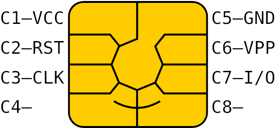
Common IC cards usually follow the ISO 7816-3 standard and have the same pinout and contact shape. Image source.
| Bus Pirate | 24C02 | Description |
|---|---|---|
| IO0/SDA | C7 - I/O | I2C Data |
| IO1/SCL | C3 - CLK | I2C Clock |
| Vout | C1 - VCC | 5volt power supply |
| GND | C5 - GND | Ground |
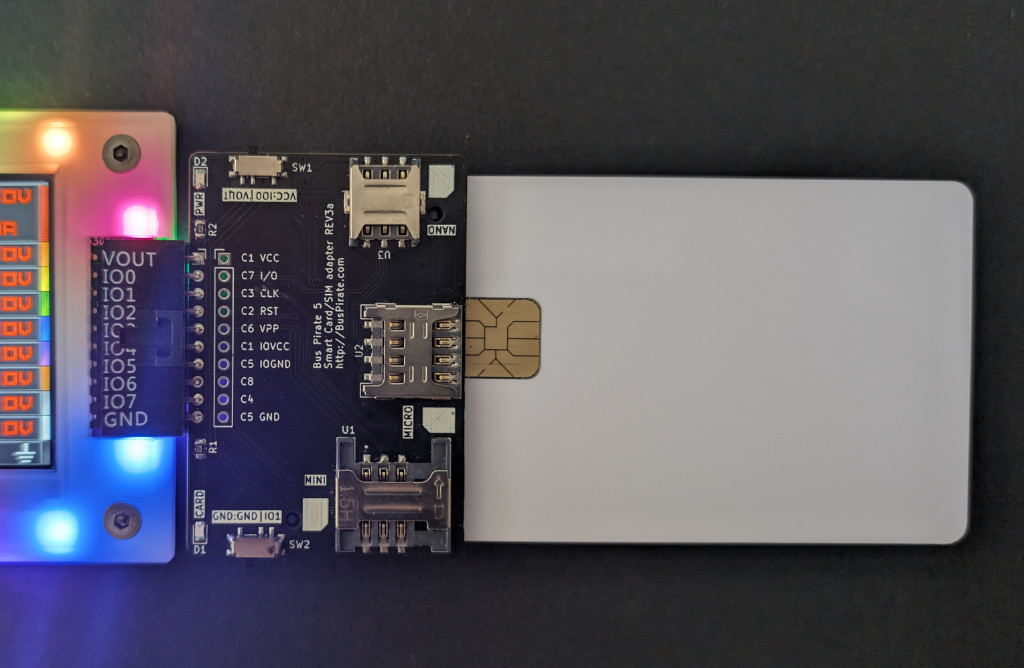
Connect the Bus Pirate to the smart card as shown in the table above.
Card Identification
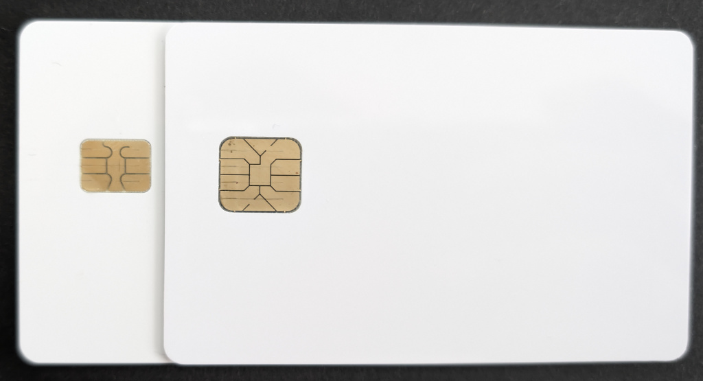
The card on the left with the smaller 6 pin contact area is a SLE4442. The card on the right with the larger 8 pin contact area is a 24C02 EEPROM card.
Smart IC Card and SIM card adapter
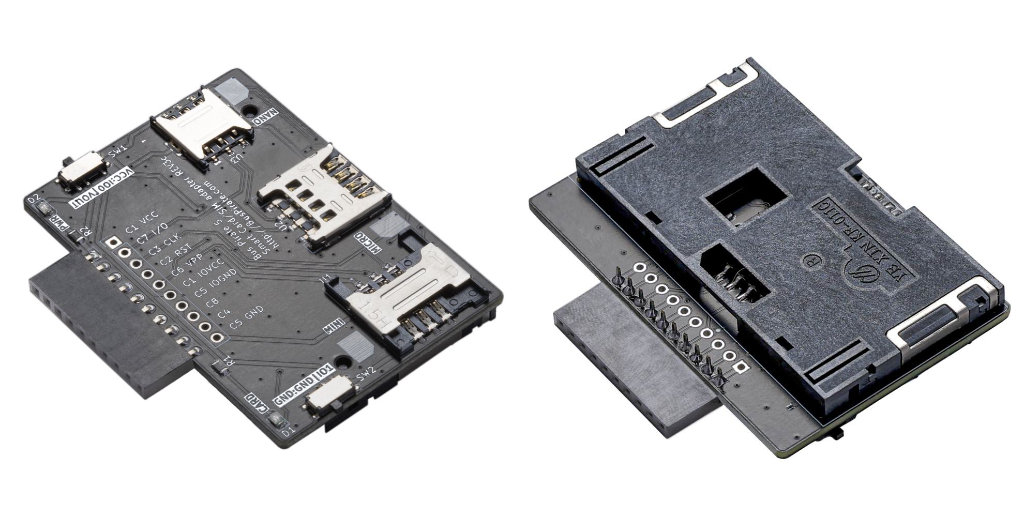
It’s possible to gently solder wires on to each pad of the chip, but a KF-011C (or similar) smart card socket is useful if you don’t want to destroy the card.
A smart IC card and SIM card adapter is available for Bus Pirate 5 with the correct connections already set. The adapter accepts most ISO 7816-3 smart cards and mini/micro/nano SIM cards.
See it in action
Setup
HiZ> m i2c

Mode: I2C
I2C speed
 1kHz to 1000kHz
 x. Exit
kHz (400kHz*) > 100
Clock stretching
 1. OFF*
 2. ON
 x. Exit
OFF (1) > 1
I2C>
24C02 IC cards use the common and friendly I2C interface. Speeds under 100kHz should work with most cards, though speed demons might try up to 400kHz.
Original I2C EEPROM cards were slow and highly limited by early EEPROM technology. The new cards available today generally use more modern EEPROM devices, but there’s no way to know exactly what modern features it may have unless the manufacturer provides a datasheet. Even a datasheet is no guarantee that the chip used in the card will match.
Power supply
I2C> W 5
5.00V requested, closest value: 5.00V
300.0mA requested, closest value: 300.0mA

Power supply:Enabled
Vreg output: 5.0V, Vref/Vout pin: 5.0V, Current: 2.6mA

I2C>
This is old tech - it needs a 5 volt power supply.
W 5- enable the onboard power supply at 5 volts.
Pull-up resistors
I2C> P
Pull-up resistors: Enabled (10K ohms @ 5.0V)

I2C>
I2C is an open collector output bus, the Bus Pirate and the 24C02 can only pull the line low to 0 (ground). A pull-up resistor is needed to pull the line high to 1 (5 volts). The Bus Pirate has built-in pull-up resistors that can be enabled with the P command.
P- Enable the onboard pull-up resistors.
Be sure to enable the pull-up resistors. The data line will never go high without them and you’ll read only 0s.
I2C address scan
I2C> scan
I2C address search:
0x50 (0xA0 W) (0xA1 R)

Found 2 addresses, 1 W/R pairs.

I2C>
Let’s see if we can find the card I2C address. We could look in the datasheet, or we can be lazy and run an I2C address scan.
scan- Scan the I2C bus for devices
The scanner found an I2C device at address 0x50 (0xA0 write, 0xA1 read). That’s the 24C02 EEPROM.
If the scanner doesn’t find the device, ensure the power supply is enabled W 5 and the pull-up resistors are enabled P. Also check that slide switches SW1 and SW2 select VOUT and GND respectively.
Write & Read Bytes
24C02 EEPROMs can read and write single bytes of data anywhere in the memory range. This may seem like a simple and obvious feature, but some EEPROMs can only write multiple byte pages.
Write Byte
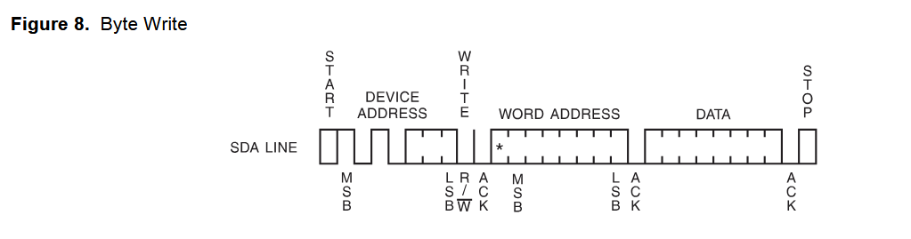
This diagram shows how to write a byte to the EEPROM.
- I2C START bit - begins an I2C transaction
- The I2C write address 0xA0 (Device Address + Write bit)
- The location to write in the 256 bytes of EEPROM (Word Address)
- The data to write
- I2C STOP bit - ends the transaction
The “Word Address” sets the location of the address pointer. The address pointer is part of the chip that keeps track of where to read or write data. The address pointer is updated to the next memory location each time a byte is read or written. At the end of the 256 bytes of memory the address pointer rolls over to 0x00.
Source: datasheet.
I2C> [0xa0 0x09 0x12]

I2C START
TX: 0xA0 ACK 0x09 ACK 0x12 ACK
I2C STOP
I2C>
First, let’s write a byte to the EEPROM. 0xa0 is the I2C write address, and let’s put our data at address 0x09 inside the EEPROM. Address 0x09 (9) is the 10th byte inside the EEPROM because the first byte is at address 0. You can write any data value between 0x00 and 0xFF (0-255), but we’ll use 0x12 (18) for the demo.
[- I2C START bit0xa0- I2C address and write bit0x09- EEPROM address pointer, address 90x12- Data to write]- I2C STOP bit
Read Byte
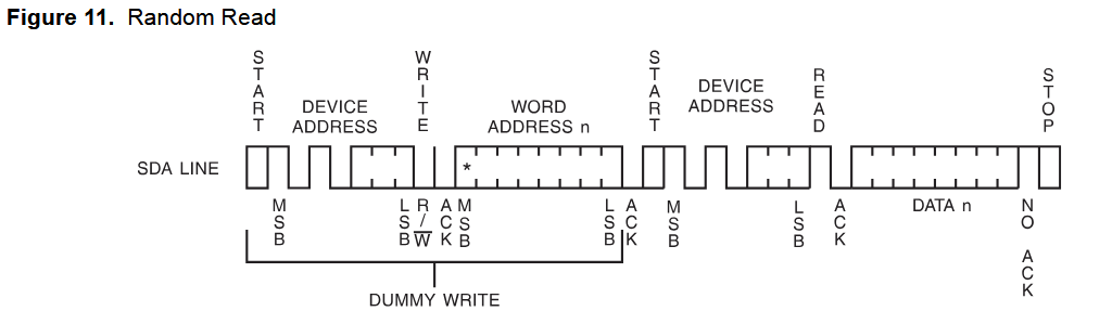
Reading a byte is a two step process.
- Set the location to read (Word Address) with a command to the write address (0xA0). This is the same sequency as writing a byte, but we don’t include any data (Dummy Write).
- Send the read address (0xA1) and read data from the EEPROM.
Reading from most I2C devices is a two step process. First we set the address pointer, then we read the data. This is a common pattern in I2C devices.
Set address pointer
I2C> [0xa0 0x9]

I2C START
TX: 0xA0 ACK 0x09 ACK
I2C STOP
I2C>
A 0xa0 write command is used to set the address pointer back to 0x09. This time we won’t include any data. The address pointer will be updated, but nothing is written to the EEPROM.
[- I2C START bit0xa0- I2C address and write bit0x09- EEPROM address pointer, address 9]- I2C STOP bit
The address pointer has been set to 0x09, the location of the data we want to read. This command didn’t include a data byte, so nothing was written to the EEPROM.
Read Byte From EEPROM
I2C> [0xa1 r]

I2C START
TX: 0xA1 ACK
RX: 0x12 NACK
I2C STOP
I2C>
Now that the address pointer is set to 0x09, we can read the data at that location using the I2C read address 0xa1.
[- I2C START bit0xa1- I2C address and read bitr- Read 1 byte]- I2C STOP bit
The data read from the EEPROM (RX:) is 0x12, the same value we wrote earlier.
We used two discrete commands to set the address pointer and read the data. This could also be done in a single sequence by omitting the I2C STOP bit between the two commands. This is called a “repeated start” and is the method shown in the diagram above. The command would look like this: [0xa0 0x09 [ 0xa1 r]. The I2C STOP bit is not needed between the two commands, but it is required at the end of the transaction.
Write & Read Page
| Page | 0 | 1 | 2 | 3 | 4 | 5 | 6 | 7 |
|---|---|---|---|---|---|---|---|---|
| 0 | 0x00 | 0x01 | 0x02 | 0x03 | 0x04 | 0x05 | 0x06 | 0x07 |
| 1 | 0x08 | 0x09 | 0x0a | 0x0b | 0x0c | 0x0d | 0x0e | 0x0f |
| 2 | 0x10 | 0x11 | 0x12 | 0x13 | 0x14 | 0x15 | 0x16 | 0x17 |
| … | … | … | … | … | … | … | … | … |
| 31 | 0xf8 | 0xf9 | 0xfa | 0xfb | 0xfc | 0xfd | 0xfe | 0xff |
Memory inside the 24C02 EEPROM is organized into 8 byte pages. We can write 8 bytes to the EEPROM with a single command, but the write must be aligned to the page boundary. This means 8 bytes can be written to addresses 0x00-0x07, 0x08-0x0F, 0x10-0x17, etc, but can never cross two pages.
If we write 8 bytes to an address in the middle of a page (0x03), the address pointer will roll over at the end of the page (0x07) and continue at the beginning of the page (0x00).
If more than 8 bytes of data are sent, the address pointer will roll over and overwrite previously sent data bytes.
Page Write Size
| Card | Write Page Size |
|---|---|
| 24C01, 24C02 | 8 bytes |
| 24C04, 24C08, 24C16 | 16 bytes |
24C02 has 32 pages of 8 bytes. 24C04 and larger EEPROMs use a 16 byte page, so more data can be written with a single command.
Always check the page size in the datasheet to avoid write errors.
Write Page
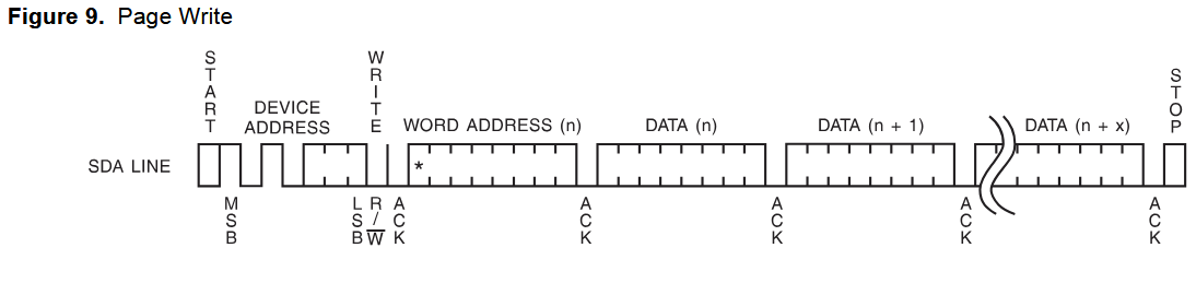
Writing a page is similar to writing a byte, but we send a page of data (8 bytes) instead of a single byte. The address pointer is set to the first byte of the page, and the data is sent in a single command.
I2C> [0xa0 0 0x12 0x34 0x56 0x78 0x9a 0xbc 0xde 0xf0]

I2C START
TX: 0xA0 ACK
TX: 0 ACK
TX: 0x12 ACK 0x34 ACK 0x56 ACK 0x78 ACK 0x9A ACK 0xBC ACK 0xDE ACK 0xF0 ACK

I2C STOP
I2C>
Let’s write 8 bytes to the first page of memory that starts at address 0x00 and ends at 0x07.
[- I2C START bit0xa0- I2C address and write bit0- EEPROM address pointer, address 0, beginning of page 00x12 0x34 0x56 0x78 0x9a 0xbc 0xde 0xf0- Data to write]- I2C STOP bit
Remember, page writes must be aligned to the page boundary. If you write to an address in the middle of a page, the address pointer will roll over to the beginning of the page.
Read Page
Reading a page (or more!) is similar to reading a byte. First we set the address pointer to the beginning of the page with a write command, then we read the data.
Set address pointer
I2C> [0xa0 0x00]

I2C START
TX: 0xA0 ACK 0x00 ACK
I2C STOP
I2C>
Set the address pointer to the beginning of page 0, address 0x00.
[- I2C START bit0xa0- I2C address and write bit0x00- EEPROM address pointer, address 0, beginning of page 0]- I2C STOP bit
Read Page From EEPROM
I2C> [0xa1 r:8]

I2C START
TX: 0xA1 ACK
RX: 0x12 ACK 0x34 ACK 0x56 ACK 0x78 ACK 0x9A ACK 0xBC ACK 0xDE ACK 0xF0 NACK

I2C STOP
I2C>
Read the 8 byte page and verify the data was written.
[- I2C START bit0xa1- I2C address and read bitr:8- Read 8 bytes]- I2C STOP bit
The data read from the EEPROM (RX:) is 0x12 0x34 0x56 0x78 0x9A 0xBC 0xDE 0xF0, the same values we wrote in the previous step.
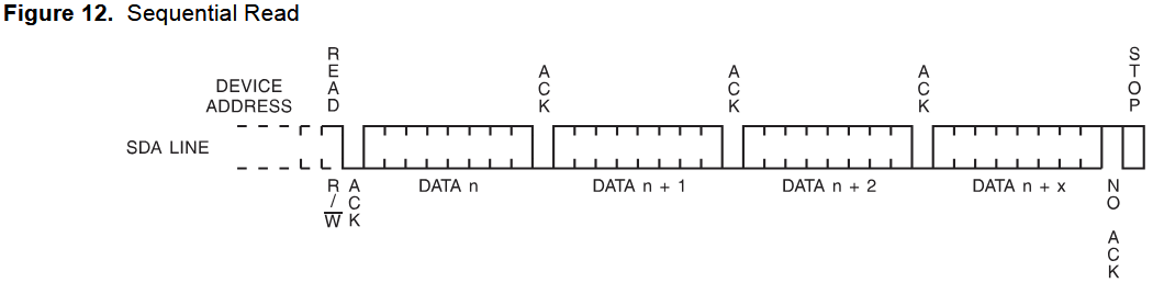
Continuous Read
The full EEPROM can be read in a single operation with a continuous read. After 256 bytes it will roll over and start reading from the beginning again.
Set address pointer
I2C> [0xa0 0x00]

I2C START
TX: 0xA0 ACK 0x00 ACK
I2C STOP
I2C>
Set the address pointer to the beginning of the EEPROM, address 0x00.
[- I2C START bit0xa0- I2C address and write bit0x00- EEPROM address pointer, address 0]- I2C STOP bit
Read Complete EEPROM
I2C> [0xa1 r:256]

I2C START
TX: 0xA1 ACK
RX: 0x12 ACK 0x34 ACK 0x56 ACK 0x78 ACK 0x9A ACK 0xBC ACK 0xDE ACK 0xF0 ACK
...lines removed....
0xFF ACK 0xFF ACK 0xFF ACK 0xFF ACK 0xFF ACK 0xFF ACK 0xFF ACK 0xFF NACK

I2C STOP
I2C>
Now we can read the entire 256 byte EEPROM in a single read step.
[- I2C START bit0xa1- I2C address and read bitr:256- Read 256 bytes]- I2C STOP bit
Other card sizes
| Card | Organization | Write Page Size | Size |
|---|---|---|---|
| 24C01 | 1 * 128 bytes | 8 bytes | 128 bytes |
| 24C02 | 1 * 256 bytes | 8 bytes | 256 bytes |
| 24C04 | 2 * 256 bytes | 16 bytes | 512 bytes |
| 24C08 | 4 * 256 bytes | 16 bytes | 1024 bytes |
| 24C16 | 8 * 256 bytes | 16 bytes | 2048 bytes |
I2C EEPROM cards are available in several common sizes. Less common sizes up to 64K are available (24C512) from a few suppliers.
I2C> scan
I2C address search:
0x50 (0xA0 W) (0xA1 R)
0x51 (0xA2 W) (0xA3 R)
0x52 (0xA4 W) (0xA5 R)
0x53 (0xA6 W) (0xA7 R)
0x54 (0xA8 W) (0xA9 R)
0x55 (0xAA W) (0xAB R)
0x56 (0xAC W) (0xAD R)
0x57 (0xAE W) (0xAF R)

Found 16 addresses, 8 W/R pairs.

I2C>
Commands are similar among 24Cxx cards. Larger cards have multiple I2C addresses that represent 256 byte memory sections. 24C16, shown here, has 256 bytes of memory at 8 different I2C address pairs.
Get a Bus Pirate
Get Bus Pirate & Accessories
- Browse Complete Bus Pirate hardware collection
- Bus Pirate 5 REV10 with enclosure
- Probe Cable Kit
- Auxiliary Cable Kit
- Quick Connect Adapter