Command Reference
The Bus Pirate is a versatile debugging and development tool for working with various communication protocols like I2C, SPI, UART, and more. It acts as a bridge between a computer and embedded devices, allowing users to talk to chips without writing code. It is especially useful for prototyping, testing, and reverse engineering hardware.
It’s always best to use the latest firmware. There are continuous improvements and new features. See the upgrade guide for the simple drag and drop update process.
User terminal
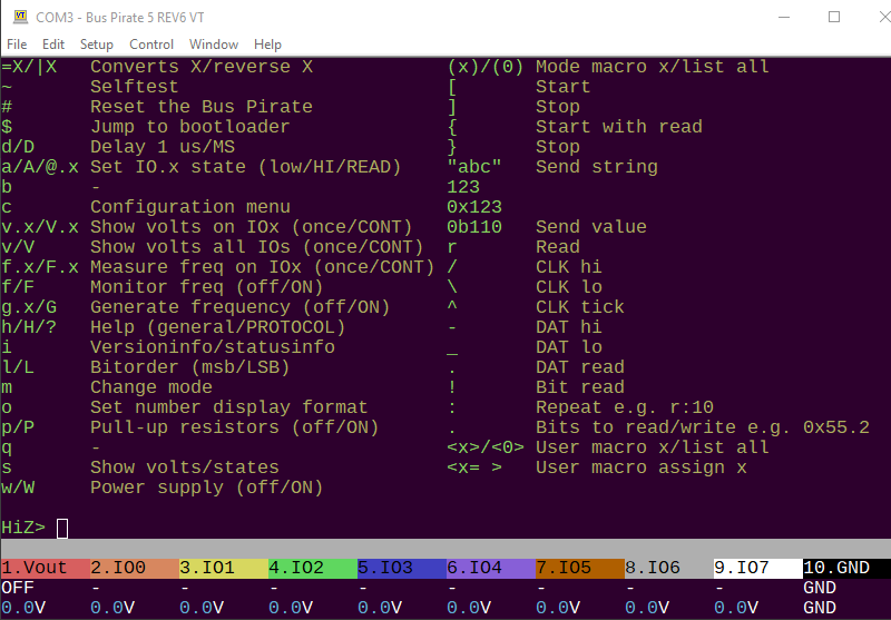
HiZ> i

This device complies with part 15 of the FCC Rules. Operation is subject to the following two conditions:
(1) this device may not cause harmful interference, and
(2) this device must accept any interference received, including interference that may cause undesired operation.

Bus Pirate 5 REV10
https://BusPirate.com/
Firmware main branch @ unknown (May 20 2025 16:04:21)
RP2040 with 264KB RAM, 128Mbit FLASH
S/N: 3317570B33CC62E4
Storage:   0.10GB (FAT16 File System)

Configuration file: Loaded
Active binmode: SUMP logic analyzer
Available modes: HiZ 1WIRE UART HDUART I2C SPI 2WIRE 3WIRE DIO LED INFRARED JTAG
Active mode: HiZ

Display format: Auto

HiZ>
Connect to the Bus Pirate command line with your favorite serial terminal software. On Windows we like the latest version of Tera Term.
Talk to the Bus Pirate from a serial terminal of your choice. The serial port is emulated over USB, so the serial port speed setting should not matter. It is traditional to use “115200bps, 8/N/1” if you need configure your terminal, but it should not actually matter.
VT100 terminal emulation
VT100 compatible color mode? (Y/n)>
Press enter to show the command prompt if your terminal is blank.
If the Bus Pirate has just restarted you will be prompted to choose the terminal emulation mode.
- VT100 mode - Supports color and a live view statusbar at the bottom of the terminal. This should be your first choice unless you specifically need the legacy ASCII mode.
- ASCII mode - Legacy monochrome text only mode.
The terminal mode can be changed from the configuration menu. Open the configuration menu with the c command followed by enter.
If you choose VT100 mode and see lots of garbage characters in the terminal, check that your terminal emulator has VT100 support and that VT100 support is enabled.
Command line
HiZ> The Bus Pirate has a simple Linux-like command line interface. Enter a command followed by optional parameters and then press enter to execute.
HiZ mode
The Bus Pirate always starts in high impedance mode (HiZ), a safe mode with all outputs disabled. HiZ mode intends to protect any connected devices from conditions beyond their specifications. From the HiZ prompt, a bus mode can be selected to use a specific protocol with the m mode command.
Terminal control
| Keyboard Key | Action |
|---|---|
left arrow | Moves the cursor left one character |
right arrow | Moves the cursor right one character |
up arrow | Copies the previous command in the command history buffer to the command line |
down arrow | Copies the next command in the command history buffer to the command line |
home | Moves the cursor to the beginning of the line |
end | Moves the cursor to the end of the line |
backspace | Erases the character to the left of the cursor and moves the cursor left one character |
delete | Erases the character under (or to the right of) the cursor and moves the cursor left one character |
The terminal understands some common control keys. Left and right move the cursor, up and down scroll through the command history. Home and end move the cursor to the beginning or end of the line. Backspace and delete erase characters.
Default options
HiZ> m i2c

Mode: I2C
I2C speed
 1kHz to 1000kHz
 x. Exit
kHz (400kHz*) >
Clock stretching
 1. OFF*
 2. ON
 x. Exit
OFF (1) >
I2C>
Most prompts have a default value shown in ( ) or marked with *, and the option to exit without making changes.
- Press
enterto select the default option. - Press
xfollowed byenterto exit a menu without changes.
Saved options
HiZ> m i2c

Mode: I2C

Use previous settings?
 I2C speed: 400 kHz
 Clock stretching: OFF

y/n, x to exit (Y) > y

I2C>
Many options will be saved to flash storage. You will be prompted to reloaded previous settings the next time.
Getting help
The latest help for commands and modes is available in the help menu. This will always be more up to date than the documentation you’re currently reading.
?orhelp- show the help menu with all available commands and options.help modeor? mode- show the help menu with all available commands and options for the current mode.<command> -h- show command specific help. For example,W -hshows help for theWcommand.
Global command list
?orhelp- show the help menu with all available commands and options.
Mode help
INFRARED-(RAW)> help mode

INFRARED mode commands:
test	Test IR RX/TX Toy plank
tvbgone	TV-B-Gone, turn off many brands of TV
irtx	Transmit IR signals (aIR format)
irrx	Receive, record, retransmit IR signals (aIR format)

INFRARED-(RAW)>
help modeor? mode- show the help menu with all available commands and options for the current mode.
Command help
I2C> W -h
usage:
w|W	<v> <i>
Disable: w
Enable, with menu: W
Enable 5v, 50mA limit: W 5 50
Enable 3.3v, 300mA default limit: W 3.3
Enable 3.3v, no limit: W 3.3 0

onboard power supply with programmable fuse
w	Disable onboard power supply
W	Enable onboard power supply, show configuration menu
<v>	Voltage, 0.8-5.0volts
<i>	Current limit, 0-500mA

I2C>
<command> -h- show command specific help. For example,W -hshows help for theWcommand.
Basic commands
| Command | Description |
|---|---|
i | Version information |
c | Configuration options menu |
m | Set bus mode |
l/L | Set MSB/LSB first |
o | Data output display format |
d | Display mode |
~ | Self-test |
reboot | Reboot the Bus Pirate |
$ | Jump to bootloader for updates |
cls | Clear and redraw terminal |
ovrclk | Overclock the CPU |
i Version information
HiZ> i

This device complies with part 15 of the FCC Rules. Operation is subject to the following two conditions:
(1) this device may not cause harmful interference, and
(2) this device must accept any interference received, including interference that may cause undesired operation.

Bus Pirate 5 REV10
https://BusPirate.com/
Firmware main branch @ unknown (May 20 2025 16:04:21)
RP2040 with 264KB RAM, 128Mbit FLASH
S/N: 3317570B33CC62E4
Storage:   0.10GB (FAT16 File System)

Configuration file: Loaded
Active binmode: SUMP logic analyzer
Available modes: HiZ 1WIRE UART HDUART I2C SPI 2WIRE 3WIRE DIO LED INFRARED JTAG
Active mode: HiZ

Display format: Auto

HiZ>
Display the hardware, firmware, and microcontroller version information. If a mode is selected, additional information about the mode is displayed.
i- show the current version information.
c Configuration options menu
HiZ> c

Configuration options
 1. Language / Jezik / Lingua / 语言
 2. ANSI color mode
 3. ANSI toolbar mode
 4. LCD screensaver
 5. LED effect
 6. LED color
 7. LED brightness
 x. Exit
 > x

Configuration file: Saved

HiZ>
Configure language, LED effects, terminal output and other options. On exit settings are saved to bpconfig.bp on the Bus Pirate flash storage.
c- show the configuration menu.x- exit the configuration menu and save the current settings to flash storage.
m Set bus mode
I2C> m

Mode selection
 1. HiZ
 2. 1WIRE
 3. UART
 4. HDUART
 5. I2C
 6. SPI
 7. 2WIRE
 8. 3WIRE
 9. DIO
 10. LED
 11. INFRARED
 12. JTAG
 x. Exit
Mode > 1
Mode: HiZ
HiZ>
The Bus Pirate starts in HiZ mode, a safe mode with all outputs disabled. The m command selects a bus mode. The Bus Pirate supports many different protocols, including I2C, SPI, UART, 1-Wire, and more. Each protocol has its own set of commands and options.
m- show the bus mode menu and change modes.
I2C> m hiz

Mode: HiZ
HiZ>
An optional mode parameter can be specified to skip the mode menu. For example, m i2c selects I2C mode.
m <mode>- change bus mode without showing the menu.
l/L Set MSB/LSB first
2WIRE> l
Bitorder: MSB 0b10000000
2WIRE> L
Bitorder: LSB 0b00000001
2WIRE>
The l/L commands determine the bit order for reading and writing bytes.
l- most significant bit (MSB) first. This is the default setting.L- least significant bit (LSB) first.
The current bit order configuration is displayed on the extended information screen using the i command while in a mode other than HiZ.
o Data output display format
2WIRE> o

Number display format
 Current setting: Auto
 1. Auto
 2. HEX
 3. DEC
 4. BIN
 5. ASCII
 x. Exit
Mode > 1
Mode: Auto
2WIRE>
The Bus Pirate can display values as hexadecimal, decimal, binary and raw ASCII bytes.
Auto display mode mirrors input formatting. Each value is displayed in the HEX/DEC/BIN format entered.
Change the setting in the data display format menu with the o command. The default display format is Auto.
o- show the data display format menu.
The current display format is shown on the extended information screen using the i command while in a mode other than HiZ.
d Display mode
HiZ> d
Display selection
 1. Default
 2. Scope
 x. Exit
Display > 2
Display: Scope
d selects the LCD display mode.
- Default: Pin labels and voltage
- Scope: Oscilloscope mode
~ Self-test
HiZ> ~
SELF TEST STARTING
DISABLE IRQ: OK
ADC SUBSYSTEM: VUSB  5.08V OK
DAC READ/WRITE: OK
FLASH STORAGE: OK
PSU ENABLE: OK
BIO FLOAT TEST (SHOULD BE 0/0.2V)
BIO0 FLOAT: 0/0.04V OK
BIO1 FLOAT: 0/0.04V OK
BIO2 FLOAT: 0/0.04V OK
BIO3 FLOAT: 0/0.04V OK
BIO4 FLOAT: 0/0.04V OK
BIO5 FLOAT: 0/0.04V OK
BIO6 FLOAT: 0/0.04V OK
BIO7 FLOAT: 0/0.04V OK
BIO HIGH TEST (SHOULD BE >3.0V)
Perform a factory self-test. The Bus Pirate is capable of twiddling pins and checking for hardware faults. See the Bus Pirate self-test guide for a complete list of tests and the problems they detect.
~- run the self-test.
Disconnect all wires and devices from the Bus Pirate before running the self-test. Any connected devices may be damaged or cause the test to fail.
Self-test is only available in HiZ mode. If you are in a different mode, the Bus Pirate will prompt you to change to HiZ mode before running the test.
reboot Reboot
HiZ> reboot

VT100 compatible color mode? (Y/n)>
Reboot the Bus Pirate.
reboot- reboot the Bus Pirate.
Depending on your serial terminal software you may need to reconnect to the Bus Pirate serial port. The latest versions of many terminal emulators, such as Tera Term, reconnect automatically.
$ Jump to bootloader
HiZ> $
Jump to bootloader for firmware upgrades

Bus Pirate 5 REV10
Firmware download:
https://forum.buspirate.com/t/bus-pirate-5-auto-build-main-branch/20/999999
Hardware revision: 10
Firmware file: bus_pirate5_rev10.uf2
A USB disk named "RPI-RP2" will appear
Drag a firmware file to the disk to upgrade
Later Alligator!
Activate the Bus Pirate bootloader for firmware updates. The bootloader appears as a USB disk drive connected to your computer. Drag a .uf2 firmware file into the disk. After an update the Bus Pirate resets. See firmware downloads and upgrade instructions.
$- jump to bootloader mode.
When jumping to bootloader mode, the Bus Pirate displays the hardware version, download link, and the name of the firmware file to use.
cls Clear and redraw terminal
HiZ> cls -h
usage:
cls
Clear and refresh the terminal screen: cls
Note: will attempt to detect and initialize VT100 ANSI terminal

HiZ>
cls- clear the screen and redraw the status bar.
Useful when connecting to an already running Bus Pirate with a new terminal window.
ovrclk Overclock the CPU
HiZ> ovrclk -h
!!ovrclk is in demonstration mode!!
To enable overclocking, recompile with BP_OVERCLOCK_ENABLED defined

usage:
ovrclk 	[-m <MHz> | -k <kHz>] [-v <core mV>]
Overclock: ovrclk -m 135
Change core voltage: ovrclk -v 1150 (850-1300mV valid)

HiZ>
ovrclk [-m <MHz> | -k <kHz>] [-v <core mV>]- set the CPU clock speed and core voltage.
ovrclk is disabled by default. It must be enabled at compile time.
Utilities
| Command | Description |
|---|---|
w/W | Power supply (off/ON) |
v/V | Power supply voltage report (once/CONTINUOUS) |
p/P | Pull-up resistors (off/ON) |
g/G | Frequency generator (off/ON) |
f/F | Measure frequency (once/CONTINUOUS) |
=X | Convert X to HEX/DEC/BIN number format |
| X | Reverse bits in byte X |
a/A/@ | Auxiliary pin control (low/HIGH/input) |
logic | Logic analyzer control |
jep106 | Lookup 2 byte JEDEC JEP106 vendor ID |
w/W Power supply (off/ON)
2WIRE> W
Power supply
Volts (0.80V-5.00V)
x to exit (3.30) > 5
Maximum current (1mA-500mA), 0 for unlimited
x to exit (300.00) > 50
5.00V requested, closest value: 5.00V
50.0mA requested, closest value: 50.0mA
Undervoltage limit: 4.50V (10%)

Power supply:  Enabled
Vreg output: 5.0V, Vref/Vout pin: 5.0V, Current: 3.1mA

2WIRE>
A ‘Programmable Power Supply Unit’ (PPSU) has several handy features:
- 1-5volts adjustable output
- 0-500mA current sense
- 0-500mA current limit with digital fuse
- Adjustable undervoltage limit to detect shorts and brownouts
- One-way valve to protect the PPSU when an external voltage is applied to the VREF/VOUT pin
Uppercase W enables the onboard power supply unit. You will be prompted for the output voltage and an optional current limit. Default current limit is 300mA, or 0 for no current limit.
Command line options: W <voltage> <current limit> -u <undervoltage limit>
| Option | Description |
|---|---|
| Voltage | Output voltage in volts (1.0 to 5.0V) |
| Current limit | Current limit in mA (0 to 500mA). 0 for no current limit. Default is 300mA. |
| Undervoltage limit | Undervoltage limit in percent (0 to 100). Default is 10. -u 100 to disable undervoltage protection. |
Examples:
W- Enable the power supply unit. Show interactive menu to set voltage and current limit.W <voltage> <current limit>- Enable the power supply unit with voltage and current limit specified.W <voltage>- Enable the power supply unit with voltage specified. Current limit is set to 300mA by default.W <voltage> 0- Enable the power supply unit with voltage specified. No current limit.W <voltage> <current limit> -u <undervoltage limit>- Enable the power supply unit with voltage, current limit and undervoltage limit (percent) specified.w- Disable the power supply unit.
Check the voltage and current in the live view statusbar if active, or show the power supply voltage report using the v command.
When the programmed current limit or undervoltage limit is exceeded the power supply is disabled. The terminal colors invert repeatedly, an alarm bell will sound, an error message is shown and command execution is halted. Use the W command to restart the PPSU again.
300mA is the rated maximum of the PPSU, but we added some headroom in the current limit to account for current spikes.
The PPSU is capable of 0.8 to 5volts output. However, the maximum working range is limited to 1-5volts because of the maximum Vgs of the P-channel MOSFET in the one-way valve. Many will be capable of the full range, but some may not. The Bus Pirate IO buffers are only rated to 1.65volts, so in practice this isn’t an issue over the specified working range.
2WIRE> W 5 50
5.00V requested, closest value: 5.00V
50.0mA requested, closest value: 50.0mA
Undervoltage limit: 4.50V (10%)

Power supply:  Enabled
Vreg output: 5.0V, Vref/Vout pin: 5.0V, Current: 3.0mA

2WIRE>
W <voltage> <current limit>- Set the voltage and current limit. The voltage is in volts, the current limit is in mA. The current limit is optional, if not specified the default is 300mA, or use 0 for no current limit.
2WIRE> w
Power supply: Disabled

2WIRE>
Lowercase w disables the PPSU.
w- Disable the power supply.
v/V Power supply voltage report

The voltage report shows the current state of all the Bus Pirate pins and peripherals. This is a duplicate of the information shown on the live view statusbar.
v- Show the power supply voltage report once.V- Show the power supply voltage report, update continuously. Press any key to exit.
p/P Pull-up resistors
I2C> P
Pull-up resistors: Enabled (10K ohms @ 3.3V)

I2C> p
Pull-up resistors: Disabled
I2C>
p and P toggle the pull-up resistors off and on. Pull-up resistors are required for open collector/open drain bus types such as 1-Wire and I2C.
P- Enable the pull-up resistors.p- Disable the pull-up resistors.
The onboard pull-up resistors are powered through the VREF/VOUT pin of the IO header, either by the onboard power supply or an external voltage applied to the VREF/VOUT pin.
A warning is displayed if there’s no voltage on the VREF/VOUT pin. Check the status bar or voltage report v to verify that a voltage is present on VOUT/VREF.
g/G Frequency generator
DIO> G
Generate frequency
Choose available pin:
 0. IO0
 1. IO1
 2. IO2
 3. IO3
 4. IO4
 5. IO5
 6. IO6
 7. IO7
 x. Exit
 > 0
Period or frequency (ns, us, ms, Hz, kHz or Mhz) > 12.4khz
Frequency: 12.400kHz = 12400Hz (12.40kHz)
Period: 80645ns (80.65us)

Actual frequency: 12401Hz (12.40kHz)
Actual period: 80640ns (80.64us)

Duty cycle (%) > 35%
Duty cycle: 35.00% = 28224ns (28.22us)
Actual duty cycle: 28227ns (28.23us)
Divider: 16, Period: 10079, Duty: 3528

Generate frequency: Enabled on IO0

DIO>
Uppercase G displays the frequency generation menu. Choose an available pin and enter the period or frequency, including the units (ns, us, ms, Hz, KHz or Mhz). Enter a duty cycle as a percent, don’t forget the %. The Bus Pirate will find the closest match and generate a frequency on the pin.
G- show the frequency generation menu.g- disable frequency generator, show menu if multiple frequency generators are active.g <pin>- disable frequency generator on <pin>.

The frequency generator will be displayed in the live view statusbar and on the LCD with the label PWM.
Not all pins will be available due to the PWM structure of the Raspberry Pi chip used in the Bus Pirate, and adjacent pairs must share the same frequency.
DIO> g
Disable frequency generation
Choose available pin:
 0. IO0
 2. IO2
 4. IO4
 x. Exit
 > 4
Generate frequency: Disabled on IO4
DIO>
g- disable frequency generator, show menu if multiple frequency generators are active.
DIO> g 0

Generate frequency: Disabled on IO0
DIO>
g <pin>- disable frequency generator on <pin>.
f/F Measure frequency
LED-()> F
Frequency measurement
Choose available pin:
 1. IO1
 3. IO3
 5. IO5
 7. IO7
 x. Exit
 > 7
Frequency measurement: Enabled on IO7
Frequency IO7: 12.40KHz 80.65us (12400Hz), Duty cycle: 35.0%

LED-()>
Frequency measurement is available on odd numbered pins (1,3,5,7). A frequency can be sampled once or continuously.
F- show the frequency measurement menu, measure continuously and display in the status bar.f- Disable continuous frequency measurement, show menu if multiple frequency generators are active.F <pin>- measure the frequency and duty cycle on pin <pin> continuously. Press any key to exit.f <pin>- measure the frequency and duty cycle on pin <pin> once.
The frequency will be measured continuously and displayed in the live view statusbar and LCD with the label FREQ.
Not all pins will be available due to the PWM structure of the Raspberry Pi chip used in the Bus Pirate, and adjacent pairs share the same PWM slice.
DIO> f
Disable frequency measurement
Choose available pin:
 1. IO1
 3. IO3
 5. IO5
 x. Exit
 > 1
Frequency measurement: Disabled on IO1
DIO>
f- Disable continuous frequency measurement, show menu if multiple frequency generators are active.
LED-()> f 7
Frequency IO7: 12.40KHz 80.65us (12400Hz), Duty cycle: 35.0%
LED-()>
f <pin>- measure the frequency and duty cycle on pin <pin> once.
LED-()> F 7
Press any key to exit
Frequency IO7: 12.40KHz 80.65us (12400Hz), Duty cycle: 35.0%
F <pin>- measure the frequency and duty cycle on pin <pin> continuously. Press any key to exit.
LED-()> f 6
IO6 has no frequency measurement hardware!
Freq. measure is currently only possible on odd pins (1,3,5,7).
Only half of the pins support frequency measurement. The Bus Pirate will warn you if hardware isn’t available. To see which pins are currently available use the F command.
=X Convert to HEX/DEC/BIN number format
DIO> = 0b1100
 =0x0C =12 =0b00001100
DIO> = 0x6
 =0x06 =6 =0b00000110
DIO> = 6
 =0x06 =6 =0b00000110
DIO>
Convert between HEX, DEC and BIN number formats easily. Type = followed by a number to see the HEX/DEC/BIN equivalent.
= <number>- Display the HEX/DEC/BIN equivalent of <number>.
To change the Bus Pirate output display format see the o command.
| X Reverse bits
DIO> | 0b11110000
 | 0x0F | 15 | 0b00001111
DIO>
Reverse bit order of a number. Displays the HEX/DEC/BIN value of the reversed number.
| <number>- Reverse the bits in <number>.
To change the Bus Pirate read/write bit order see the l/L command.
a/A/@ Auxiliary pin control (low/HIGH/read)
DIO> a 1
IO1 set to OUTPUT: 0

DIO> A 1
IO1 set to OUTPUT: 1

DIO> @ 1
IO1 set to INPUT: 0

DIO>
Pins that are not assigned a function can be controlled from the command line.
a <pin>- set IO <pin> low (0V).A <pin>- set pin X high (VCC).@ <pin>- set pin X to input (HiZ) and read the pin state. The pin state is reported as 0 or 1.
Pins already assigned a function, such as PWM or mode/protocol pins, cannot be changed with the a/A/@ commands. The Bus Pirate will report an error.
Commands a/A/@ are followed by a space and the pin number to control. This is different than syntax a/A/@ which use the a.<pin> notation.
logic Logic analyzer control
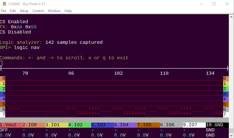
The logic command configures the logic analyzer core, and can display logic capture graphs directly in the terminal. It supports the “follow along” logic analyzer mode that triggers each time you send data to a bus. It eliminates the need setup triggers and arm a second tool for debugging.
The Bus Pirate can be used as a logic analyzer in multiple ways:
- PulseView and the SUMP interface
- PulseView With the “follow along logic analyzer” interface
- Directly in the terminal with the
logiccommand
HiZ> logic -h
usage:
logic analyzer usage
logic	[start|stop|hide|show|nav]
	[-i] [-g] [-o oversample] [-f frequency] [-d debug]
start logic analyzer: logic start
stop logic analyzer: logic stop
hide logic analyzer: logic hide
show logic analyzer: logic show
navigate logic analyzer: logic nav
configure logic analyzer: logic -i -o 8 -f 1000000 -d 0
undocumented: set base pin (0=bufdir, 8=bufio) -b: logic -b 8

logic analyzer control
start	start logic analyzer
stop	stop logic analyzer
hide	hide logic graph
show	show logic graph
nav	navigate logic graph with arrow keys, x to exit
-i	show configuration info
-o	set oversample rate, multiplies the sample frequency
-f	set sample frequency in Hz
-0	set character used for low in graph (ex:_)
-1	set character used for high in graph (ex:*)
-d	set debug level: 0-2
-h	Get additional help

HiZ>
jep106 Lookup JEP106 vendor ID
HiZ> jep106 -h
usage:
jep106 <bank number> <vendor id>
Lookup JEP106 ID (Micron): jep106 0x00 0x2c
Lookup JEP106 ID (Sinker): jep106 0x0a 0xab

lookup vendor name from 2 byte JEDEC JEP106 ID code
-h	help for Bus Pirate commands and modes

HiZ> jep106 0x00 0x2c
JEP106 Bank: 0x00, ID: 0x2C => Manufacturer: Micron Technology

HiZ> jep106 0x0a 0xab
JEP106 Bank: 0x0A, ID: 0x2B => Manufacturer: Sinker

HiZ>
There are several types of JEDEC manufacturer/vendor IDs. A 2 byte JEP106 ID is commonly used in flash, NAND and other chips. The Bus Pirate can lookup 2 byte JEP106 IDs with the jep106 command.
jep106 <bank number> <vendor ID>- Lookup a two byte JEP106 vendor ID
The first byte of a JEP106 ID is the bank number where the vendor ID is found. Currently only the lower 4 bits are used, yielding 16 banks numbered 0-15.
Byte 2 is the vendor ID, a number in the range of 1-126. Finding the vendor ID in the correct bank gives us the vendor name.
JEP106 vendor IDs are limited to the range of 1 to 126. To include more than 126 vendors, the list is divided into 16 banks (currently) of 126 vendors each.
Here are some fun facts about vendor ID numbers:
Vendor ID is 7 bits and 1 indexed (not 0!). So there are 126 vendor IDs in each bank (0x01 to 0x7e)
Vendor ID 0x00 is invalid (indexed from 1)
IF the bank is 0 then vendor ID bit 7 will be 0. Thus vendor IDs in bank 0 range from 0x01 to 0x7e.
IF the bank is greater than 0 vendor ID bit 7 will be 1. Thus vendor IDs in bank 1+ range from 0x81 to 0xff.
Disk Commands
Linux-like commands are used to navigate the flash storage from the Bus Pirate command line.
| Command | Description |
|---|---|
ls | List files and directories |
cd | Change directory |
mkdir | Make directory |
rm | Remove file or directory |
cat | Print file contents as text |
hex | Print file contents in HEX |
format | Format storage disk (FAT16) |
label | Get or set the disk label |
dump | Perform multiple reads with the r command, save to a file |
image | Display a bitmap image file on the LCD |
These common commands are supported in the firmware as of this update, but always use help or ? to see the latest commands available. Add -h to any command for extended help: hex -h.
ls List directory contents
HiZ> ls
        39 bpi2c.bp
0 dirs, 1 files

HiZ>
List the contents of a directory in flash storage.
ls- list the contents of the current directory.ls <directory>- ls followed by a directory name lists the contents of that directory.
mkdir Make directory
HiZ> mkdir test

HiZ> ls
        39 bpi2c.bp
   <DIR>   test
1 dirs, 1 files

HiZ>
Make a new directory at the current location in the flash storage.
mkdir <directory>- create a new directory.
cd Change directory
HiZ> cd test
/TEST

HiZ> ls
0 dirs, 0 files

HiZ>
Change directory.
cd <directory>- change to a subdirectory.cd ..- change to the parent directory.
rm Remove file or directory
HiZ> ls
        39 bpi2c.bp
   <DIR>   test
1 dirs, 1 files

HiZ> rm test

HiZ> ls
        39 bpi2c.bp
0 dirs, 1 files

HiZ>
Remove file or directory (if empty).
rm <file | directory>- remove a file or empty directory.
label Set disk label
HiZ> label set my_pirate

HiZ> label get
disk label: MY_PIRATE
HiZ>
Set and get the disk label.
label set <label>- set the disk label. The label can be up to 11 characters long and must not contain spaces or special characters.label get- display the current disk label.
format Erase and format disk
HiZ> format
Erase the internal storage?
y/n> y
Are you sure?
y/n> y

Formatting...
Format success!
Storage mounted:    0.10 GB FAT16


HiZ>
Erase the internal flash storage and format it with a FAT16 file system. ALL DATA WILL BE LOST!
format- format the entire flash storage, confirm twice. This will erase all files and directories on the disk.
dump Dump read data to file
HiZ> dump -h
usage:
dump <bytes> <file>
First, manually setup a read from the device
Then, run this command to read X bytes to a file
Read X bytes to a file: dump 256 example.bin

HiZ>
dump <bytes> <file>- read data using the current moderbus command and save it to a file.
dump is the equivalent of using the r command to read data from a device, but instead of displaying the data on the terminal, it saves it to a file.
This command is useful when you want to save data from a device to a file. While the Bus Pirate has commands to dump many chips, the dump command is a generic read command that can be used with any device.
First, manually send the commands to put the target device in read mode. Then use the dump command to read the data and save it to a file.
image Display bitmap image on LCD
HiZ> image -h
usage:
Read BMP info and display image file on LCD
Usage: image <file> [-d] [-h]
Read info: image example.bmp
Draw on display: image example.bmp -d
Read formats: BITMAPINFOHEADER V1 (40Bytes), V2 (52B), V3 (54B)
Draw formats: 16-bit (565) and 24-bit bitmaps, 240x320 pixels
-h	Get additional help

HiZ>
image <file>- shows the header info from ANY recognized BMP format (v1/2/3)image <file> -d- draw the file content on the LCD. Checks if the file is the correct height/width and a supported pixel format (16bits/565, or 24bit/888)
Load a bitmap image file and display it on the LCD. The Bus Pirate supports BMP format images. The image must be 128x64 pixels in size, and the pixel format must be 16bits/565 or 24bit/888.
cat Print file contents
HiZ> cat bpi2c.bp
{
"baudrate": 400,
"clock_stretch": 0
}

HiZ>
Print the contents of a file.
cat <file>
hex Hex dump file
HiZ> hex bpi2c.bp

Start address: 0x00000000, end address: 0x00000026, total bytes: 39

          00 01 02 03 04 05 06 07 08 09 0A 0B 0C 0D 0E 0F
--------------------------------------------------------
00000000: 7B 0A 22 62 61 75 64 72 61 74 65 22 3A 20 34 30 |{."baudrate": 40|
00000010: 30 2C 0A 22 63 6C 6F 63 6B 5F 73 74 72 65 74 63 |0,."clock_stretc|
00000020: 68 22 3A 20 30 0A 7D                            |h": 0.}         |


HiZ>
hex <file>
HEX values 0x00 and 0xFF are printed in white, over values are printed in blue. Printable ACSII characters are yellow, non printable characters are white.
HEX dump part of a file
HiZ> hex eeprom.bin -s 0x57 -b 32

Start address: 0x00000050, end address: 0x0000007F, total bytes: 48

          00 01 02 03 04 05 06 07 08 09 0A 0B 0C 0D 0E 0F
--------------------------------------------------------
00000050: FF FF FF FF FF FF FF FF FF FF FF FF FF FF FF FF |................|
00000060: 48 65 6C 6C 6F 21 FF FF FF FF FF FF FF FF FF FF |Hello!..........|
00000070: FF FF FF FF FF FF FF FF FF FF FF FF FF FF FF FF |................|


HiZ>
-s <start address> and -b <bytes> options can be used to print a part of the file in hexadecimal format.
hex <file> -s <start address> -b <bytes>
The HEX display always aligns to a 16 byte boundary. Leading and trailing bytes you didn’t request are dark grey.
HEX dump quiet flag
HiZ> hex eeprom.bin -s 0x57 -b 32 -q

Start address: 0x00000050, end address: 0x0000007F, total bytes: 48

00 01 02 03 04 05 06 07 08 09 0A 0B 0C 0D 0E 0F
----------------------------------------------
FF FF FF FF FF FF FF FF FF FF FF FF FF FF FF FF
48 65 6C 6C 6F 21 FF FF FF FF FF FF FF FF FF FF
FF FF FF FF FF FF FF FF FF FF FF FF FF FF FF FF


HiZ>
Many HEX editor tools allow you to paste HEX values directly. The -q option suppresses the header and footer, so you can copy multiple lines from the terminal and paste the output directly into a HEX editor.
hex <file> -q- print the file in HEX format without the header and footer.
HEX command options
HiZ> hex -h
usage:
hex <file> [-s <start address>] [-b <bytes>] [-p (disable pager)] [-a (disable address column)]
Print file contents in HEX: hex example.bin
Print 32 bytes starting at address 0x50: hex example.bin -s 0x50 -b 32
Disable address and ASCII columns: hex example.bin -q
press 'x' to quit pager

Print file contents in HEX format
<file>	Name of file in 8.3 format (example1.bin)
-s	Dump start address
-b	Bytes to dump
-q	Quiet mode, disable address and ASCII columns
-p	Disable the pager for dumping

HiZ>
| Flag | Description |
|---|---|
-s <start address> | Start address to read from. Default is 0x00. |
-b <bytes> | Number of bytes to read. Default is all. |
-q | Quiet mode, no address or ASCII columns. Useful for copying HEX values to a HEX editor. |
Software support
The Bus Pirate has two USB serial ports.
- One is used for the command line terminal.
- The other supports support software running on a PC (binmode).
“binmode” supports a variety of protocols and software.
- SUMP logic analyzer protocol for sigrok/PulseView
- Binmode test framework
- Arduino CH32V003 SWIO
- Follow Along Logic Analyzer protocol for sigrok/PulseView
- Legacy Binary Mode for Flashrom and AVRdude
- aIR for AnalysIR.
binmode Change binary mode
HiZ> binmode

Select binary mode
 1. SUMP logic analyzer
 2. Binmode test framework
 3. Arduino CH32V003 SWIO
 4. Follow along logic analyzer
 5. Legacy Binary Mode for Flashrom and AVRdude (EXPERIMENTAL)
 6. IRMAN IR decoder (LIRC, etc)
 7. AIR capture (AnalysIR, etc)
 x. Exit
 >
Use the binmode command see the currently supported binary modes and to select the active binmode.
PulseView logic analyzer
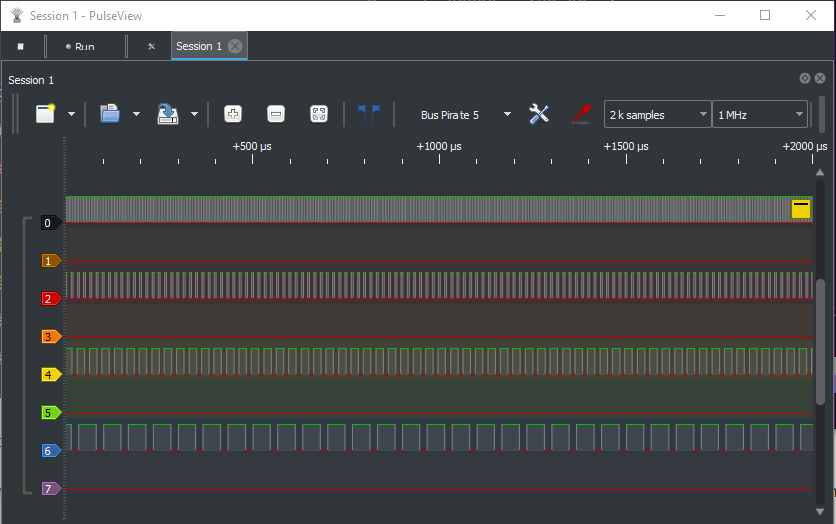
Two modes are available for the PulseView logic analyzer. The SUMP mode is the default and is compatible with the SUMP protocol. The FALADATA mode is a custom protocol for the Bus Pirate.
AVRdude AVR programmer
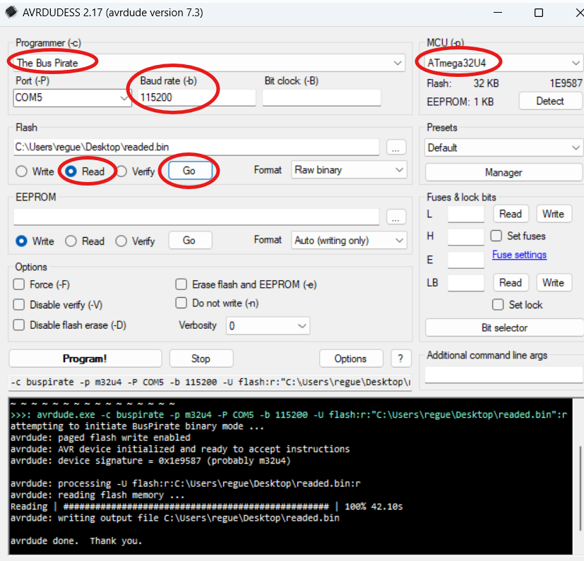
The Bus Pirate can serve as a programmer and dumper for AVR chips, using the command-line utility AVRDUDE.
For those who prefer a graphical user interface, AVRDUDESS offers a user-friendly front-end for AVRDUDE. Both tools together provide a powerful setup for working with AVR chips.
Flashrom flash programmer
flashrom.exe --progress -V -c "W25Q64JV-.Q" -p buspirate_spi:dev=COM54,serialspeed=115200,spispeed=1M -r flash_content.binThe Bus Pirate can serve as a programmer and dumper for flash memory chips, using the command-line utility Flashrom.
Flashrom is a versatile utility for identifying, reading, writing, verifying, and erasing flash chips on a wide range of devices—including mainboards, controller cards, and various programmer modules. It supports hundreds of flash chips, chipsets, and boards.
AnalysIR Infrared remote decoder
Scripting commands
| Command | Description |
|---|---|
macro | Load a set of macros |
script | Run a script |
button | Assign scripts to the button |
pause | Pause and wait for user input |
There are multiple ways to script actions on the Bus Pirate.
macro Load a set of macros
Macros are single line commands stored in a text file. The macro file can be changed as needed, so you can have different sets of macros for different tasks.
# This is my example macro file
#! Enable power supply 3.3V, 100mA limit
1:W 3.3 100
#! Read 5 bytes from an I2C EEPROM
2:[0xa0 0][0xa1 r:5]
Formatting is simple:
- Lines starting with
#are comments. - Lines starting with
#!are macro help/descriptions. - Lines starting with a number and a colon (
1:) are macros. The number is the macro ID, and the text after the colon is the command to execute.
HiZ> macro -f macros.mcr
Set macro file: 'macros.mcr'
Set the active macro file with the -f <file> flag.
HiZ> macro -l
'macros.mcr' available macros:

#! Enable power supply 3.3V, 100mA limit
1:W 3.3 100
#! Read 5 bytes from an I2C EEPROM
2:[0xa0 0][0xa1 r:5]
List the macros in the active macro file with the -l flag.
HiZ> macro 1
Exec macro id: 1
W 3.3 100
Execute a macro by its ID number.
| Flag | Description |
|---|---|
-f <file> | Set the macro file to <file> |
-l | List the macros in the active macro file |
-h | Show help |
script Run a script
HiZ> script -h
usage:
script <file> [-p(ause for <enter>)] [-d (hiDe comments)] [-e(xit on error)] [-h(elp)]
Run script: script example.scr

Script files:
Script files are stored in text files with the .scr extension
Lines starting with '#' are comments
Other lines are inserted into the command prompt
Example:
# This is my example script file
# The 'pause' command waits for any key press
pause
# Did it pause?

HiZ>
Script files are simple text files with one command per line.
Lines starting with # are comments. Comments are displayed by default, but can be supressed with the -d flag.
# This is my example script file
# The 'pause' command waits for any key press
pause
# Did it pause?
This example uses the pause command to wait for user input.
HiZ> script example.scr
# This is my example script file
# The 'pause' command waits for any key press
HiZ> pause
Press any key

# Did it pause?
To exit a running script type x.
Scripts can only inject commands into the command line, not prompts or menus.
# Enable power supply
W 3.3 50
This script works, everything is entered on the command line.
# Show power supply menu
W
# Set 3.3 volts
3.3
# Set current limit to 50mA
50
This script does not work. Scripts cannot answer menu prompts.
| Flag | Description |
|---|---|
-p | Pause at each line, press enter to continue |
-d | Do not display comments |
-x | Exit the script on error |
-h | Show help |
button Assign scripts to the button
HiZ> button -h
usage:
button [short|long] [-f <file>] [-d (hiDe comments)] [-e(xit on error)] [-h(elp)]
Assign script file to short button press: button short -f example.scr
Assign script file to long button press: button long -f example.scr
Exit script on error option: button short example.scr -e
Default script files are 'button.scr' and 'buttlong.scr' in the root directory

Assign script file to button press
short	Assign script file to short button press
long	Assign script file to long button press
-f	Script file to assign to button press
-d	Hide comments
-e	Exit script on error
-h	Get additional help

HiZ>
Scripts can be assigned to the Bus Pirate button. Scripts are the same format used with the script command above.
- By default short presses run
button.scr - By default long presses run
buttlong.scr
Use the button command to change the script assigned to button presses, configure comment display, and set error handling.
Button settings do not persist after a reboot.
| Flag | Description |
|---|---|
-f <file> | Set the script file to run on button press |
-d | Do not display comments |
-x | Exit the script on error |
-h | Show help |
pause Pause and wait for user input
HiZ> pause -h
usage:
pause and wait for any key: pause
pause and wait for button press: pause -b
pause and wait for button or any key: pause -b -k
'x' key to exit (e.g. script mode): pause -x

Pause for user input, optional exit
-k	Press any key to continue (default)
-b	Press the Bus Pirate button to continue
-x	'x' key to exit (e.g. script mode)
-h	Get additional help

HiZ>
pause- pause and wait for user input. Press any key to continue.
Pause and wait for user input. Useful for pausing during a script or macro.
| Flag | Description |
|---|---|
-k | Pause for any key press (default) |
-b | Pause for button press |
-x | Allow escape from scripts whit the ‘x’ key |
Developer commands
| Command | Description |
|---|---|
bug | Replicate a silicon bug |
otpdump | Dump the OTP memory |
dummy | Template for new commands |
A set of command useful or used during development. These commands are not intended for end users, but are available in the firmware.
bug Replicate silicon bugs
HiZ> bug -h
usage:
replicate hardware bugs
Test errata E9: bug e9
-h	Get additional help

HiZ>
bug <errata>- replicate a silicon bug in the Raspberry Pi Chip.
This command is used for testing and debugging purposes.
otpdump Dump OTP memory (BP 6+)
HiZ> otpdump -h
Invalid command: otpdump. Type ? for help.
HiZ>
otpdump- dump the OTP memory of the Raspberry Pi chip.
Valid only on RP2350 or later chips with OTP memory (Bus Pirate 6+).
dummy New command template
HiZ> dummy -h
usage:
dummy [init|test]
	[-b(utton)] [-i(nteger) <value>] [-f <file>]
Initialize: dummy init
Test: dummy test
Test, require button press: dummy test -b
Integer, value required: dummy -i 123
Create/write/read file: dummy -f dummy.txt
Kitchen sink: dummy test -b -i 123 -f dummy.txt

Dummy commands valid in position 1
init	Dummy init command
test	Dummy test command

Dummy flags
-b	-b require Bus Pirate button to be pushed. Takes no parameters
-i	-i <integer>. Requires integer number parameter
-f	-f <file>. Create/write/read <file>. Requires file string parameter

HiZ>
dummy is a template that demonstrates how to create a new command.
If you want to add a new command to the Bus Pirate firmware, you can use this template as a starting point.
Bus commands
| Command | Description | Command | Description |
|---|---|---|---|
[/{ | Bus START condition | ^ | Clock pin tick |
> | Execute bus commands (no START) | / | Clock pin high |
]/} | Bus STOP condition | \ | Clock pin low |
r | Read byte | - | Data pin high |
0b01 | Write this binary value | _ | Data pin low |
0x01 | Write this HEX value | . | Read data pin |
0d01 | Write this DEC value | ||
"abc" | Write this ASCII string | ||
| Value delimiter | ||
d/D | Delay (us/ms) | ||
: | Repeat command | ||
. | Specify bits to read/write | ||
v.<pin> | Read voltage on <pin> | ||
a.<pin>/A.<pin>/@.<pin> | Auxillary pin control (low/HIGH/input) |
SPI> [0x31 r:5]
CS Select (0)
TX: 0x31
RX: 0x00 0x00 0x00 0x00 0x00
CS Deselect (1)
SPI>
A simple bus commands are used to interact with devices in various protocols. Bus command characters have the same general function in each bus mode, such as r to read a byte of data.
This example sends a bus start, the value 0x31, and then reads 5
bytes, followed by bus stop. Up to 255 characters may be
entered into the Bus Pirate terminal at once, press enter to execute the
commands.
Bus commands must start with [, {, or >.
[ or { Bus START condition
SPI> [
CS Select (0)
SPI>
START commands generate a START condition (I2C), a RESET (1-Wire, LED), chip select (SPI) and have similar START type functions in most modes. A line beginning with START is interpreted as bus commands.
[- send the START condition for the currently selected bus mode.{- send the alternate START condition for the currently selected bus mode.
Check the protocol documentation below to see what START and alternate START do in each mode. In SPI mode, for example, [ selects a chip, while { selects the chip and displays each byte received when data is written (write with read mode).
Lines beginning with [ and { are interpreted as bus commands, data will be sent to the device in the current protocol selected with the m command.
> Execute bus commands (no START)
SPI> > 0x55 0xaa

TX: 0x55 0xAA
SPI>
If you want to execute bus commands without sending a START, use the > bus command. Lines beginning with > are also executed as bus commands.
>- start a line with>to send bus commands without sending a START condition.
The > command is used to send syntax without sending a START command to the bus.
] or } Bus STOP condition
SPI> >]
CS Deselect (1)
SPI>
Many protocols have a STOP condition. In various modes ] and } STOPs (I2C), deselects
(SPI), or closes (UART).
]- send the STOP condition for the currently selected bus mode.}- send the alternate STOP condition for the currently selected bus mode.
r Read byte
SPI> >r
RX: 0x00
SPI>
r- read a byte from the bus. Use with the repeat command (r:1…255) for bulk reads.
The > before r tells the Bus Pirate we want to send bus commands.
0b01 Write this binary value
SPI> >0b01
TX: 0b00000001
SPI>
Binary values are commonly used in electronics because the 1s and 0s correspond to register ‘switches’ that control various aspects of a device. When used as part of a bus command, the Bus Pirate will write the value in the currently selected bus protocol.
Begin a binary number with 0b, followed by the bits. Padding 0’s are not required,
0b00000001=0b1. Can be used with the repeat command (0b110:1…255) for bulk writes.
0b0- binary “0”.0b1- binary “1”.0b11111111- binary “255”.
The > before 0b01 tells the Bus Pirate we want to send bus commands.
0x01 Write this HEX value
SPI> >0x01
TX: 0x01
SPI>
Hexadecimal values are base 16 numbers that use a-f for the numbers 10-15, this format is very common in computers and electronics. When used as part of a bus command, the Bus Pirate will write the value in the currently selected bus protocol.
Begin a hexadecimal number with 0x or 0h, followed by the hex digits. A-F can be lowercase or uppercase letters. Padding 0’s are not required, 0x05=0x5. Hexadecimal numbers can be used with the repeat command (0xff:1…255) for bulk writes.
0x0- hexadecimal “0”.0x1- hexadecimal “1”.0xff- hexadecimal “255”.
The > before 0x01 tells the Bus Pirate we want to send bus commands.
0-255 Write this decimal value
SPI> >1
TX: 1
SPI>
Any number not started with 0b, 0x or 0h is interpreted as a decimal value. Decimal values are common base 10 numbers. Just enter the value, no special prefix is required. Decimal numbers can be used with the repeat command (10:1…255) for bulk writes.
0- decimal “0”.1- decimal “1”.255- decimal “255”.
The > before 1 tells the Bus Pirate we want to send bus commands.
"abc" Write this ASCII string
SPI> >"abc"
TX: 'a' 0x61 'b' 0x62 'c' 0x63
Characters enclosed in " " are sent to the bus as their ASCII equivalent codes. Useful for writing text strings when programming flash chips, interfacing UARTs, etc.
"abc"- Write the ASCII string “abc” to the bus, equivalent to 0x61 0x62 0x63.
The > before "abc" tells the Bus Pirate we want to send bus commands.
space Value delimiter
SPI> [1 2 3  rr]
CS Select (0)
TX: 1
TX: 2
TX: 3
RX: 0x00
RX: 0x00
CS Deselect (1)
SPI>
Use a space to separate numbers.
- space is used to separate numbers on the command line.
No delimiter is required between non-number commands.
d/D Delay 1uS/MS
SPI> >d
Delay: 1us
SPI> >d:10
Delay: 10us
SPI> >D
Delay: 1ms
SPI> >D:10
Delay: 10ms
SPI>
Delay in microseconds or milliseconds. Delays can be extended with the repeat command (d:1…255).
d- delays 1us.d:10- delay 10us.D- delays 1ms.D:10- delay 10ms.
The > before d tells the Bus Pirate we want to send bus commands.
: Repeat (e.g. r:10)
SPI> [ 0x55:2 D:3 r:3]
CS Select (0)
TX: 0x55 0x55
Delay: 2ms
RX: 0x00 0x00 0x00
CS Deselect (1)
SPI>
Many commands can be repeated by adding :, followed by the number of times to repeat. To read five bytes, enter r:5, etc.
0x55:2- write 0x55 to the bus twice.D:3- delay 3ms.r:3- read 3 bytes from the bus.
Repeat values can also be HEX/DEC/BIN formatted.
. Specify number of bits to read/write
SPI> >0x5a.4
TX: 0x0A.4
SPI>
Write/read partial bytes (where enabled by hardware) using the . option. 0x75.4 will write 0x5 (4 bits) to the bus.
SPI> >r.4
RX: 0x05.4
SPI>
Read 4 bits from the bus.
SPI> >0x5432.12
TX: 0x0432.12
SPI>
Write 12 bits of 0x5432 to the bus.
SPI> >0x5a.4:2
TX: 0x0a.4 0x0a.4
SPI>
Partial write/reads can be combined with the repeat command.
v Measure voltage
SPI> > v.1 v.2 v.3

Volts on IO1: 3.2V
Volts on IO2: 3.2V
Volts on IO3: 3.2V
SPI>
It is possible to measure the voltage of any IO pin while executing bus commands.
v.<pin>- measure the voltage on IO pin <pin>
The > before v.1 v.2 v.3 tells the Bus Pirate we want to send bus commands.
a/A/@ Auxiliary pin control (low/HIGH/read)
UART> >a.1
IO1 set to OUTPUT: 0

UART> >A.1
IO1 set to OUTPUT: 1

UART> >@.1
IO1 set to INPUT: 0

UART>
Sometimes it’s useful to control IO pins directly when executing bus commands.
a.<pin>- set <pin> low (0V).A.<pin>- set <pin> high (VCC).@.<pin>- set <pin> to input (HiZ) and read the pin state. The pin state is reported as 0 or 1.
Pins already assigned a function, such as PWM or mode/protocol pins, cannot be changed with the a/A/@ commands. The Bus Pirate will report an error.
Bus commands a/A/@ use the a.<pin> notation, the syntax is followed by a . and the pin number to control. This is different than the commands a/A/@, which are followed by a space and the pin number to control.
^ Clock pin tick (limited)
2WIRE> >^

Tick clock: 1
2WIRE>
Send a single clock tick to the bus. The clock pin is set high (VCC) for a short time, then set low (0V).
“Bitwise” commands provide low-level control over the clock and data pins, allowing precise manipulation of their states. These commands are only available in specific modes, such as 2WIRE and 3WIRE.
/ Clock pin high (limited)
2WIRE> >/

Set clock: 1
2WIRE>
Set the clock pin high (VCC).
\ Clock pin low (limited)
2WIRE> >\

Set clock: 0
2WIRE>
Set the clock pin low (0V).
- Data pin high (limited)
2WIRE> >-

Set data: 1
2WIRE>
Set the data pin high (VCC).
_ Data pin low (limited)
2WIRE> >_

Set data: 0
2WIRE>
Set the data pin low (0V).
. Read data pin (limited)
2WIRE> >.

Read data: 0
2WIRE>
Read the current state of the data pin.
Supported bus protocols
| HiZ | 1WIRE | UART |
| HDUART | I2C | SPI |
| 2WIRE | 3WIRE | DIO |
| LED | INFRARED | JTAG |
The Bus Pirate supports a variety of bus protocols. Each protocol has its own set of commands and features. Select a protocol with the m command.
Several protocols have sub modes such as LED and INFRARED.
Always update to the latest firmware as protocols are frequently improved and new protocols added.
HiZ
- Bus: High impedance (HiZ)
- Connections: none
- Output type: not allowed
- Pull-up resistors: not allowed
- Maximum voltage: 5 volts
HiZ is the default Bus Pirate mode. It is a safe mode: all outputs and hardware are disabled.
To change into a protocol mode, use the m command.
HiZ is a safe mode. If something goes wrong with your target device, switch to safe mode to disable all outputs and hardware.
1-Wire
- Bus: 1-Wire
- Connections: one data pin (OWD) and ground
- Output type: open drain/open collector
- Pull-up resistors: always required (2K - 10K ohms)
- Maximum voltage: 5volts
1-Wire is a single wire bus for low speed interfaces.
Pull-up resistors
1-Wire is an open-collector bus, it requires pull-up resistors to hold the data line high and create the data ‘1’. 1-Wire parts don’t output high, they only pull low. Without pull-up resistors there can never be a ‘1’.
Enable the Bus Pirate onboard pull-up resistors with the P command.
1-Wire requires a pull-up resistor to hold the data line high.
1-Wire parts don’t output high, they only pull low.
Without pull-up resistors there can never be a ‘1’.
Enable the Bus Pirate onboard pull-up resistors with the
Pcommand.
Connections
| Bus Pirate | Direction | Circuit | Description |
|---|---|---|---|
| OWD | ↔ | OWD | 1-Wire Data |
| GND | ⏚ | GND | Signal Ground |
Bus commands
| Command | Description |
|---|---|
| { or [ | Issue 1-Wire reset, detect device presence. |
| r | Read one byte. (r:1…255 for bulk reads) |
| 0b | Write this binary value. Format is 0b00000000 for a byte, but partial bytes are also fine: 0b1001. |
| 0x | Write this HEX value. Format is 0x01. Partial bytes are fine: 0xA. A-F can be lower-case or capital letters. |
| 0-255 | Write this decimal value. Any number not preceded by 0x or 0b is interpreted as a decimal value. |
space | Value delimiter. Use a space to separate numbers. No delimiter is required between non-number values: {0xa6 0 0 16 5 0b111 0xaF rrrr}. |
Other Commands
Global commands are available everywhere, while mode commands are specific to the currently selected mode. Type help to see all commands in every mode, or help mode for the currently available mode commands.
Most Bus Pirate commands have extended help. Add the -h flag to any command to see the latest available options and usage examples.
scan 1-Wire address search
1WIRE> scan
1-Wire ROM search:
1: 28 5c aa 13 0a 00 00 19 (DS18B20 digital thermometer)

1WIRE>
scan- perform a 1-Wire ROM search.
scan performs a 1-Wire ROM search to detect the ID of every connected 1-Wire device. The type of device is shown if the family ID is known.
eeprom Read, write, erase, verify, test, dump 1-Wire EEPROMs
eeprom is a command to read, write, erase, verify, test and dump common GX/DS243x 1-Wire EEPROMs.1-Wire EEPROM list supported devices
1WIRE> eeprom list

Available EEPROM devices:
Device	|Bytes	|Page Size	|Addr Bytes	|Blk Sel Bits	|kHz max
DS2431	|128	|8		|2		|0		|16
DS2433	|512	|32		|2		|0		|16

Compatible with common 1-Wire EEPROMs: DS/GX2431. 2433 untested!
3.3volts is suitable for most devices.

1WIRE>
eeprom list- list all EEPROM devices supported by theeepromcommand
| Device | Size | Bytes | Page Size | Addr Bytes | Blk Sel Bits | kHz max |
|---|---|---|---|---|---|---|
| DS2431/GX2431 | 1K | 128 | 8 | 2 | 0 | 16 |
| DS24B33 | 4K | 512 | 32 | 2 | 0 | 16 |
There are only two widely used 1-Wire EEPROM: DS2431+ (1Kbit) and DS24B33 (4Kbit). There is also a clone of the DS2431+ called GX2431.
The eeprom command uses the “skip ROM” method to access the EEPROM. This means that only one EEPROM can be connected to the 1-Wire bus at a time. If you have multiple EEPROMs, you must disconnect all but one before using the eeprom command.
Chip voltage requirements
| Family | Minimum Voltage | Maximum Voltage | |
|---|---|---|---|
| DS243X | 2.8V | 5.25V |
Before using the eeprom command, you’ll need to enable a power supply with the W command and pull-up resistors with the P command.
1-Wire EEPROMs are powered from the bus data line, not a supply pin. If EEPROM writes fail you may need to add a 2K or smaller pull-up resistor between a power supply (VOUT) and the 1-Wire data pin.
1-Wire EEPROM dump to terminal
1WIRE> eeprom dump -d ds2431 -s 0x06 -b 32
DS2431: 128 bytes,  0 block select bits, 2 byte address, 8 byte pages

Start address: 0x00000000, end address: 0x0000002F, total bytes: 48

          00 01 02 03 04 05 06 07 08 09 0A 0B 0C 0D 0E 0F
---------------------------------------------------------
00000000: 55 AA 55 AA 55 AA 55 AA 55 AA 55 AA 55 AA 55 AA |U.U.U.U.U.U.U.U.|
00000010: 55 AA 55 AA 55 AA 55 AA 55 AA 55 AA 55 AA 55 AA |U.U.U.U.U.U.U.U.|
00000020: 55 AA 55 AA 55 AA 55 AA 55 AA 55 AA 55 AA 55 AA |U.U.U.U.U.U.U.U.|

1WIRE>
Display the contents of an EEPROM in the terminal.
eeprom dump -d <device>- display EEPROM contentseeprom dump -d <device> -s <start>- display EEPROM contents, starting at address<start>eeprom dump -d <device> -s <start> -b <bytes>- display a specific range of bytes, starting at address<start>and reading<bytes>bytes
1-Wire EEPROM read to file
1WIRE> eeprom read -d ds2431 -f eeprom.bin -v
DS2431: 128 bytes,  0 block select bits, 2 byte address, 8 byte pages

Read: Reading EEPROM to file eeprom.bin...
Progress: [###########################] 100.00%
Read complete
Read verify...
Progress: [###########################] 100.00%
Read verify complete
Success :)

1WIRE>
Read the contents of an EEPROM and save it to a file.
eeprom read -d <device> -f <file>- read EEPROM contents to file<file>eeprom read -d <device> -f <file> -v- read EEPROM contents to file<file>, verify the read operation
1-Wire EEPROM write from file
1WIRE> eeprom write -d ds2431 -f eeprom.bin -v
DS2431: 128 bytes,  0 block select bits, 2 byte address, 8 byte pages

Write: Writing EEPROM from file eeprom.bin...
Progress: [###########################] 100.00%
Write complete
Write verify...
Progress: [###########################] 100.00%
Write verify complete
Success :)

1WIRE>
eeprom write -d <device> -f <file>- write EEPROM from file<file>eeprom write -d <device> -f <file> -v- write EEPROM from file<file>, verify the write operation
If the file is bigger than the EEPROM, only the first bytes of the file will be written to the EEPROM. The rest of the file will be ignored.
If the file is smaller than the EEPROM, the full file will be written to the EEPROM, and the rest of the EEPROM will be left unchanged. The eeprom command will read the target page from the EEPROM, write the new data to the page, and then write the full page back to the EEPROM. This is done to avoid writing partial pages, which some devices cannot handle.
1-Wire EEPROM verify against file
1WIRE> eeprom verify -d ds2431 -f eeprom.bin
DS2431: 128 bytes,  0 block select bits, 2 byte address, 8 byte pages

Verify: Verifying EEPROM contents against file eeprom.bin...
Progress: [###########################] 100.00%
Verify complete

1WIRE>
eeprom verify -d <device> -f <file>- verify EEPROM contents against file<file>
If the file is bigger than the EEPROM, only the first bytes of the file will be verified against the EEPROM. The rest of the file will be ignored.
If the file is smaller than the EEPROM, the full file will be verified against the EEPROM, and the rest of the EEPROM will be ignored.
1-Wire EEPROM erase
1WIRE> eeprom erase -d ds2431 -v
DS2431: 128 bytes,  0 block select bits, 2 byte address, 8 byte pages

Erase: Writing 0xFF to all bytes...
Progress: [###########################] 100.00%
Erase complete
Erase verify...
Progress: [###########################] 100.00%
Erase verify complete
Success :)

1WIRE>
Erase the contents of an EEPROM, writing 0xFF to all bytes.
eeprom erase -d <device>- erase EEPROM contentseeprom erase -d <device> -v- erase EEPROM contents, verify the erase operation
1-Wire EEPROM test
1WIRE> eeprom test -d ds2431
DS2431: 128 bytes,  0 block select bits, 2 byte address, 8 byte pages

Erase: Writing 0xFF to all bytes...
Progress: [###########################] 100.00%
Erase complete
Erase verify...
Progress: [###########################] 100.00%
Erase verify complete

Test: Writing alternating patterns
Writing 0xAA 0x55...
Progress: [###########################] 100.00%
Write complete
Write verify...
Progress: [###########################] 100.00%
Write verify complete
Writing 0x55 0xAA...
Progress: [###########################] 100.00%
Write complete
Write verify...
Progress: [###########################] 100.00%
Write verify complete
Success :)

1WIRE>
Test EEPROM functionality. Erase the EEPROM to 0xff and verify the erase. Then write alternating patterns of 0xAA and 0x55, verifying each write operation. Any stuck bits should be detected during the test.
test -d <device>- test EEPROM functionality
1-Wire EEPROM show protection status
1WIRE> eeprom protect -d ds2431
DS2431: 128 bytes,  0 block select bits, 2 byte address, 8 byte pages

Page 0 Protection (0x080): Unprotected (0x00)
Page 1 Protection (0x081): Unprotected (0x00)
Page 2 Protection (0x082): Unprotected (0x00)
Page 3 Protection (0x083): Unprotected (0x00)
Copy Protection (0x084): Unprotected (0x00)
Factory Byte (0x085): Write Protect 0x085, Unprotect 0x086, 0x087 (0x55)
User/Manufacturer ID0 (0x086): 0x00
User/Manufacturer ID1 (0x087): 0x00

1WIRE>
eeprom protection -d <device>- show the protection status of the EEPROM
1-Wire EEPROM options and flags
1WIRE> eeprom -h
usage:
eeprom [dump|erase|write|read|verify|test|list|protect]
	[-d <device>] [-f <file>] [-v(verify)] [-s <start address>] [-b <bytes>] [-h(elp)]
List available EEPROM devices: eeprom list
Display contents: eeprom dump -d ds2431
Display 16 bytes starting at address 0x10: eeprom dump -d ds2431 -s 0x10 -b 16
Erase, verify: eeprom erase -d ds2431 -v
Write from file, verify: eeprom write -d ds2431 -f example.bin -v
Read to file, verify: eeprom read -d ds2431 -f example.bin -v
Verify against file: eeprom verify -d ds2431 -f example.bin
Test chip (full erase/write/verify): eeprom test -d ds2431
Show write protect control block: eeprom protect -d ds2431

read, write and erase 243X series 1-Wire EEPROM chips
dump	Show contents
erase	Erase chip
write	Write file to chip
read	Read chip to file
verify	Verify chip against file
test	Erase and write chip with dummy data, verify
list	List supported EEPROM devices
protect	Show chip write protect status
-f	File to write, read or verify
-v	Verify after read, write or erase
-s	Dump start address
-b	Bytes to dump
-h	Get additional help

1WIRE>
| Option | Description |
|---|---|
eeprom list | List all supported EEPROM devices |
eeprom dump | Dump EEPROM contents to terminal.Space to continue, x to exit. |
eeprom read | Read EEPROM contents to file |
eeprom write | Write EEPROM from file |
eeprom verify | Verify EEPROM contents against file |
eeprom erase | Erase EEPROM contents, writing 0xFF to all bytes |
eeprom test | Test EEPROM functionality, erase and write alternating patterns |
eeprom protect | Show the write protection status of the EEPROM |
Options tell the eeprom command what to do.
Always check the latest options and flags with eeprom -h to see the most up-to-date features.
| Flag | Description |
|---|---|
-d <device> | Specify the EEPROM device type, e.g. 24x02 |
-f <file> | Specify the file for read, write and verify |
-v | Verify the read or write operation |
-s <start> | Specify the start address for dump operations |
-b <bytes> | Specify the number of bytes to read for dump operations |
-q | Dump quiet mode, no address or ASCII columns. Useful for copying HEX values to a HEX editor. |
-c | Dump: disable paging, display all data in one go. |
-h | Show help for the eeprom command |
Flags pass file names and other settings.
ds18b20 Read temperature
1WIRE> ds18b20
RX: 7b 01 00 00 7f ff 05 10 e5
Temperature: 23.688

1WIRE>
ds18b20- read the temperature from a single DS18B20 device.
ds18b20 reads the temperature from a single 18B20 temperature sensor. The temperature is displayed in Celsius.
The device is accessed with the skip ROM command, so it will only work with a single DS18B20 device connected.
Device demos
UART
- Bus: UART, MIDI (universal asynchronous receiver transmitter)
- Connections: two data pins (RX/TX) and ground
- Output type: push-pull (1.65-5volts). Powered by onboard supply or an external voltage on the VOUT/VREF pin
- Maximum Voltage: 5volts
UART is also known as the common PC serial port. The PC serial port operates at full RS232 voltage levels (-13volts to +13volts) though, which are not compatible with the Bus Pirate without an RS232 adapter.
Connections
| Bus Pirate | Direction | Circuit | Description |
|---|---|---|---|
| TX | → | RX | Bus Pirate Transmit |
| RX | ← | TX | Bus Pirate Receive |
| GND | ⏚ | GND | Signal Ground |
Connect the Bus Pirate transmit pin (TX) to the UART device receive pin (RX). Connect the Bus Pirate receive pin (RX) to the UART device transmit pin (TX).
Configuration options
HiZ> m uart

Mode: UART
UART speed
 1200, 2400, 4800, 9600, 19200, 38400, 57600, 115200 etc
 x. Exit
Baud (115200*) >
Data bits
 5 to 8 bits
 x. Exit
Bits (8*) >
Parity
 1. None*
 2. Even
 3. Odd
 x. Exit
Parity (1) >
Stop bits
 1. 1*
 2. 2
 x. Exit
Bits (1) >
Hardware flow control
 1. None*
 2. RTS/CTS
 x. Exit
Flow control (1) >
Signal inversion
 1. Non-inverted (Standard)*
 2. Inverted
 x. Exit
Invert signals (1) >
Actual speed: 115207 baud
UART>
Bus commands
| Command | Description |
|---|---|
| [ | Open UART, use r to read bytes. |
| { | Open UART, display data as it arrives asynchronously. |
| ] or } | Close UART. |
| r | Check UART for byte, or fail if empty. (r:1…255 for bulk reads) |
| 0b | Write this binary value. Format is 0b00000000 for a byte, but partial bytes are also fine: 0b1001. |
| 0x | Write this HEX value. Format is 0x01. Partial bytes are fine: 0xA. A-F can be lower-case or capital letters. |
| 0-255 | Write this decimal value. Any number not preceded by 0x or 0b is interpreted as a decimal value. |
space | Value delimiter. Use a space to separate numbers. No delimiter is required between non-number values: {0xa6 0 0 16 5 0b111 0xaF rrrr}. |
Other Commands
Global commands are available everywhere, while mode commands are specific to the currently selected mode. Type help to see all commands in every mode, or help mode for the currently available mode commands.
Most Bus Pirate commands have extended help. Add the -h flag to any command to see the latest available options and usage examples.
bridge USB to serial bridge
UART> bridge -h
usage:
bridge	[-h(elp)] [-t(oolbar)]
Transparent UART bridge: bridge
Exit: press Bus Pirate button

open UART with raw data IO, usb to serial bridge mode
-t	ENABLE toolbar while bridge is active (default: disabled)
-h	Get additional help

UART>
UART> bridge
UART bridge. Press Bus Pirate button to exit.
$GPGSV,1,1,00*79
$BDGSV,1,1,00*68
$GNRMC,,V,,,,,,,,,,M*4E
$GNVTG,,,,,,,,,M*2D
$GNZDA,,,,,,*56
$GPTXT,01,01,01,ANTENNA OK*35
Transparent UART bridge. Acts as a USB to serial converter between the UART on the IO pins and the USB serial port used by the Bus Pirate terminal.
- Use directly with devices that have a terminal interface (example: routers)
- Exit your terminal program to use the port with a script or software (example: programming a chip, GPS software)
Press the Bus Pirate button to exit.
The UART bridge is between the Bus Pirate UART pins and the USB serial port used by the Bus Pirate terminal. To use the UART brige with a script or software, exit your terminal program first and then use the same port with your application. The bridge is NOT active on the secondary USB serial port used by binmode.
Use bridge -h to see the latest options and features.
gps Decoding GPS NMEA sentences
UART> gps -h
usage:
gps	[-h(elp)]
Decode GPS NMEA packets: gps
Exit: press any key

parse NMEA GPS data
-h	Get additional help

UART>
Most GPS modules output NMEA sentences through a serial UART. The gps command decodes common sentences using minmea. The raw data and decoded data are printed in the terminal. Press any key to exit.
gpscommand UART tutorial and examples
Use gps -h to see the latest options and features.
glitch Glitch hacking framework
UART> glitch -h
usage:
glitch	[-h(elp)] [-c(onfig)]
UART glitch generator.  Note that times are in terms of nanoseconds * 10; therefore, a setting of 3 = 30ns
Exit: press Bus Pirate button

UART glitcher
-h	Get additional help
-c	show configuration info

UART>
A glitch hacking framework.
MIDI
MIDI is a command set used by electronic (music) instruments. It travels over a standard serial UART configured for 31250bps/8/n/1.
MIDI is a ring network, each node has an input and output socket. Each node passes messages to the next in the ring. The input and outputs are opto-isolated. The signaling is at 5volts, 5ma (current-based signaling). An adapter is required: example 1, example 2.
Device demos
HDUART
- Bus: Half-duplex UART, MIDI (universal asynchronous receiver transmitter), RX and TX on the same wire
- Connections: one data pin (RXTX) and ground
- Output type: open collector/open drain
- Pull-up resistors: always required (2K - 10K ohms)
- Maximum Voltage: 5volts
Half-duplex UART is a common serial UART, but receive and transmit share a single data line. This is used to interface mobile phone SIM cards and bank IC cards, among other devices.
Connections
| Bus Pirate | Direction | Circuit | Description |
|---|---|---|---|
| RXTX | ←→ | RXTX | Bus Pirate Transmit and Receive |
| GND | ⏚ | GND | Signal Ground |
Configuration options
HiZ> m hduart

Mode: HDUART
UART speed
 1200, 2400, 4800, 9600, 19200, 38400, 57600, 115200 etc
 x. Exit
Baud (115200*) >
Data bits
 5 to 8 bits
 x. Exit
Bits (8*) >
Parity
 1. None*
 2. Even
 3. Odd
 x. Exit
Parity (1) >
Stop bits
 1. 1*
 2. 2
 x. Exit
Bits (1) >
HDUART>
Pull-up resistors
Half-duplex UART is an open-collector bus, it requires pull-up resistors to hold the data line high to create the data ‘1’. The Bus Pirate doesn’t output high, it only pulls low. Without pull-up resistors there can never be a ‘1’.
Enable the Bus Pirate onboard pull-up resistors with the P command.
Half-duplex UART requires pull-up resistors to hold the data line high.
Without pull-up resistors there can never be a ‘1’.
Enable the Bus Pirate onboard pull-up resistors with the
Pcommand.
Bus commands
| Command | Description |
|---|---|
| [ | Open UART, display data as it arrives asynchronously. |
| ] | Close UART. |
| { | RST pin (IO2) high |
| } | RST pin (IO2) low |
| r | Check UART for byte, or fail if empty. (r:1…255 for bulk reads) |
| 0b | Write this binary value. Format is 0b00000000 for a byte, but partial bytes are also fine: 0b1001. |
| 0x | Write this HEX value. Format is 0x01. Partial bytes are fine: 0xA. A-F can be lower-case or capital letters. |
| 0-255 | Write this decimal value. Any number not preceded by 0x or 0b is interpreted as a decimal value. |
space | Value delimiter. Use a space to separate numbers. No delimiter is required between non-number values: {0xa6 0 0 16 5 0b111 0xaF rrrr}. |
Other Commands
Global commands are available everywhere, while mode commands are specific to the currently selected mode. Type help to see all commands in every mode, or help mode for the currently available mode commands.
Most Bus Pirate commands have extended help. Add the -h flag to any command to see the latest available options and usage examples.
bridge USB to serial bridge
HDUART> bridge -h
usage:
bridge	[-h(elp)]
Transparent UART bridge: bridge
Exit: press Bus Pirate button

open UART with raw data IO, usb to serial bridge mode
-t	ENABLE toolbar while bridge is active (default: disabled)
-s	Suppress local echo, don't echo back sent data
-h	Get additional help

HDUART>
Transparent UART bridge. Bidirectional UART pass-through to interact with other serial devices from inside the Bus Pirate terminal. Press the Bus Pirate button to exit. Useful for reading SIM cards with pySim.
Use bridge -h to see the latest options and features.
Device demos
I2C
- Bus: I2C (eye-squared-see or eye-two-see)
- Connections: two data pins (SDA/SCL) and ground
- Output type: open drain/open collector
- Pull-up resistors: always required (2K - 10K ohms)
- Maximum voltage: 1.2 to 5 volts
- Common speed: 100kHz, 400kHz, 1MHz
I2C Protocol Overview
I2C (Inter-Integrated Circuit) is a 2-wire protocol used for communication between devices. It uses two lines: SDA (data) and SCL (clock). The protocol supports multiple devices on the same bus, with each device identified by a unique 7-bit address.
Start and Stop Conditions
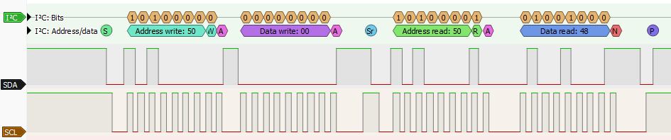
S- Each transaction begins with a start condition by pulling SDA low while SCL remains high.P- Each transaction ends with a stop condition by releasing SDA high while SCL remains high.Sr- A repeat start condition starts a new transaction with the same device, without sending a stop condition. It can be replaced with a stop condition followed by a start condition, but the repeat start is more efficient.
Byte Transmission
- Data is transmitted 8 bits at a time, starting with the most significant bit (MSB).
A/N- After each byte there is a 9th ACK/NACK bit. The receiver sends an ACK (acknowledge) by pulling SDA low or a NACK (not acknowledge) by leaving SDA high. NACK is typically used to tell a chip that we are done reading data from it.
Addressing
- The first byte sent after a start condition contains the 7-bit device address and a read/write bit. In the logic analyzer trace the 7-bit address is 0b1010000 (0x50).
W-0for write operations (0b10100000= 0xA0).R-1for read operations (0b10100001= 0xA1).
Bus Pirate I2C syntax
I2C> [0xa0 0x00 [0xa1 r]

I2C START
TX: 0xA0 ACK 0x00 ACK
I2C REPEATED START
TX: 0xA1 ACK
RX: 0x48 NACK
I2C STOP
I2C>
[0xA0 0x00 [0xA1 r] is the Bus Pirate syntax for the I2C example above.
[- I2C start condition0xA0- Write the device address0xA0, which is the 7-bit address0x50with the write/read bit cleared (0).0x00- Write the command0x00, which is often used to select a register or address.[- I2C repeat start condition.0xA1- Write the device address0xA1, which is the 7-bit address0x50with the write/read bit set (1).r- Read one byte from SDA, which will be the data from the device.]- I2C stop condition.
Configuration options
HiZ> m i2c

Mode: I2C
I2C speed
 1kHz to 1000kHz
 x. Exit
kHz (400kHz*) >
Clock stretching
 1. OFF*
 2. ON
 x. Exit
OFF (1) >
I2C>
Pull-up resistors
I2C is an open-collector bus, it requires pull-up resistors to hold the clock and data lines high and create the data ‘1’. I2C parts don’t output high, they only pull low, without pull-up resistors there can never be a ‘1’. This will cause common errors such as the I2C address scanner reporting a response at every address.
Enable the Bus Pirate onboard pull-up resistors with the P command.
I2C requires pull-up resistors to hold the clock and data lines high.
I2C parts don’t output high, they only pull low.
Without pull-up resistors there can never be a ‘1’.
Enable the Bus Pirate onboard pull-up resistors with the
Pcommand.
Connections
| Bus Pirate | Direction | Circuit | Description |
|---|---|---|---|
| SDA | ↔ | SDA | Serial Data |
| SCL | → | SCL | Serial Clock |
| GND | ⏚ | GND | Signal Ground |
Bus commands
| Command | Description |
|---|---|
| { or [ | Issue (repeated) I2C start condition. |
| ] or } | Issue I2C stop condition. |
| r | Read one byte, send ACK. (r:1…255 for bulk reads) |
| 0b | Write this binary value, check ACK. Format is 0b00000000 for a byte, but partial bytes are also fine: 0b1001. |
| 0x | Write this HEX value, check ACK. Format is 0x01. Partial bytes are fine: 0xA. A-F can be lower-case or capital letters. |
| 0-255 | Write this decimal value, check ACK. Any number not preceded by 0x or 0b is interpreted as a decimal value. |
space | Value delimiter. Use a space to separate numbers. No delimiter is required between non-number values: {0xa6 0 0 16 5 0b111 0xaF rrrr}. |
Other Commands
Global commands are available everywhere, while mode commands are specific to the currently selected mode. Type help to see all commands in every mode, or help mode for the currently available mode commands.
Most Bus Pirate commands have extended help. Add the -h flag to any command to see the latest available options and usage examples.
scan I2C address search
I2C> scan
I2C address search:
0x50 (0xA0 W) (0xA1 R)
0x51 (0xA2 W) (0xA3 R)
0x52 (0xA4 W) (0xA5 R)
0x53 (0xA6 W) (0xA7 R)
0x54 (0xA8 W) (0xA9 R)
0x55 (0xAA W) (0xAB R)
0x56 (0xAC W) (0xAD R)
0x57 (0xAE W) (0xAF R)

Found 16 addresses, 8 W/R pairs.

I2C>
The scan command searches for I2C device addresses.
You can find the I2C address for most I2C-compatible chips in the datasheet. But what if you’re working with an unknown chip, a dated chip with no datasheet or you’re just too lazy to look it up?
I2C> scan -h
usage:
scan	[-v(erbose)] [-h(elp)]
Scan I2C address space: scan
Scan, list possible part numbers: scan -v

scan I2C addresses, with optional part number
-v	Verbose mode, print potential part numbers
-h	Get additional help

I2C>
The Bus Pirate has a built-in address scanner that checks every possible I2C address for a response. This brute force method is a fast and easy way to see if any chips are responding, and to uncover undocumented access addresses.
I2C chips respond to a 7bit address, so up to 128 devices can share the same two communication wires. An additional bit of the address determines if the operation is a write to the chip (0), or a read from the chip (1).
Scanner details
The scan command in I2C mode runs the address scanner.
- For I2C write addresses: the BP sends a start, the write address, looks for an ACK, then sends a stop.
- For I2C read addresses: the BP sends a start, the read address, looks for an ACK. If there is an ACK, it reads a byte and NACKs it. Finally it sends a stop.
When the I2C chip responds to the read address, it outputs data and will miss a stop condition sent immediately after the read address (bus contention). If the I2C chip misses the stop condition, the address scanner will see ghost addresses until the read ends randomly. By reading a byte after any read address that ACKs, we have a chance to NACK the read and properly end the I2C transaction.
sniff I2C bus sniffer
I2C> sniff -h
usage:
sniff [-q]
Start the I2C sniffer: sniff
Supress (quiet) ACK in output: sniff -q

pico-i2c-sniff by @jjsch-dev https://github.com/jjsch-dev/pico_i2c_sniffer
Max speed: 500kHz

I2C sniffer
q	Quiet mode, don't show ACKs
h	Get additional help

I2C>
Sniff I2C packets up to 500kHz.
| Flag | Description |
|---|---|
-q | Supress (quiet) ACK in output |
-r | Print (raw) data, no ‘[’,’]’,‘R’‘W’ |
-7 | Use 7-bit addressing in output (default is 8-bit) |
-h | Show help for the i2c sniff command |
i2c Generic dump register command
I2C> i2c dump -a 0x50 -w 1 -r 0x00 -b 64

          00 01 02 03 04 05 06 07 08 09 0A 0B 0C 0D 0E 0F  0123456789ABCDEF
----------------------------------------------------------|----------------|
00000000: 48 65 6C 6C 6F 20 57 6F 72 6C 64 21 FF FF FF FF |Hello World!....|
00000010: FF FF FF FF FF FF FF FF FF FF FF FF FF FF FF FF |................|
00000020: FF FF FF FF FF FF FF FF FF FF FF FF FF FF FF FF |................|
00000030: FF FF FF FF FF FF FF FF FF FF FF FF FF FF FF FF |................|

I2C>
Many I2C devices follow the same pattern to read the contents of the chip registers or memory. Send the device write address followed by a register address to begin reading from. Then send the device read address and read data, the register address increments as each byte is read.
The i2c command implements this common pattern to dump I2C device contents to the terminal or read them to a file.
The address register width generally depends on the device size. Small devices (256 bytes or less) often use a 1-byte address register. Larger devices (EEPROMs, sensors, etc) often use a 2-byte address register. Some devices use 3 or 4 byte address registers. Check the device datasheet for details.
| Option | Description |
|---|---|
| dump | Dump I2C device contents to terminal. Space to continue, x to exit |
| read | Read I2C device contents to file |
Options tell the i2c command what to do.
| Flag | Description |
|---|---|
| -a | Specify the 7-bit I2C device address, e.g. 0x50 |
| -w | Specify the address register width in bytes (1-4, default 1) |
| -r | Specify the starting register address (default 0x00) |
| -f | Specify the file for read |
| -b | Dump: specify the number of bytes to read |
| -q | Dump: quiet mode, no address or ASCII columns. Useful for copying HEX values to a HEX editor. |
| -c | Dump: disable paging, display all data in one go. |
| -h | Show help for the i2c command |
Flags pass file names and other settings.
eeprom Read, write, erase, verify, test, dump I2C EEPROMs
eeprom is a command to read, write, erase, verify, test and dump common 24x I2C EEPROMs.
You do need to specify the device type, there is no non-destructive autodetect method for I2C EEPROMs.
I2C EEPROM list supported devices
I2C> eeprom listeeprom list- list all EEPROM devices supported by theeepromcommand
See Indentifying I2C EEPROM Chips for more information on chip markings, power requirements, and other details.
| Device | Size | Size (bytes) | Page Size | Address Bytes | Block Select Bits | Block Select Bit Offset |
|---|---|---|---|---|---|---|
| 24x01 | 1 Kbit | 128 | 8 | 1 | 0 | |
| 24x02 | 2 Kbit | 256 | 8 | 1 | 0 | |
| 24x04 | 4 Kbit | 512 | 16 | 1 | 1 | 0 |
| 24x08 | 8 Kbit | 1024 | 16 | 1 | 2 | 0 |
| 24x16 | 16 Kbit | 2048 | 16 | 1 | 3 | 0 |
| 24x32 | 32 Kbit | 4096 | 32 | 2 | 0 | |
| 24x64 | 64Kbit | 8192 | 32 | 2 | 0 | |
| 24x128 | 128 Kbit | 16384 | 64 | 2 | 0 | |
| 24x256 | 256 Kbit | 32768 | 64 | 2 | 0 | |
| 24x512 | 512 Kbit | 65536 | 128 | 2 | 0 | |
| 24x1025 | 1 Mbit | 131072 | 128 | 2 | 1 | 3 |
| 24x1026 | 1 Mbit | 131072 | 128 | 2 | 1 | 0 |
| 24xM01 | 1 Mbit | 131072 | 256 | 2 | 1 | 0 |
| 24xM02 | 2 Mbit | 262144 | 256 | 2 | 2 | 0 |
24x chips have a variety of part numbers, but tend to operate in the same way. Often a manufacturer specific part number indicates a different voltage range or upgraded features. AT24C, 24C, 24LC, 24AA, 24FC are all generally part of same basic 24x family of chips.
The default I2C address for most 24x chips is 0x50, but many have pins for setting a different address. The eeprom command uses 0x50 by default, but you can specify a different I2C address with the -a flag.
Chip voltage requirements
| 24xx Family | Minimum Voltage | Maximum Voltage | Notes |
|---|---|---|---|
| AT24C | 2.7V | 5.5V | 400kHz max |
| 24C | 2.7V | 5.5V | 400kHz max |
| 24LC | 2.5V | 5.5V | 400kHz max |
| 24AA | 1.7V | 5.5V | 400kHz max |
| 24FC | 1.8V | 5.5V | 1MHz max |
Before using the eeprom command, you’ll need to enable a power supply with the W command and pull-up resistors with the P command.
Most EEPROMs should be fine with a 3.3 volt power supply, but if possible check the datasheet to be sure!
I2C EEPROM dump to terminal
I2C> eeprom dump -d 24x02 -s 0x50 -b 64
24X02: 256 bytes,  0 block select bits, 1 byte address, 8 byte pages

Start address: 0x00000050, end address: 0x0000008F, total bytes: 64

          00 01 02 03 04 05 06 07 08 09 0A 0B 0C 0D 0E 0F
---------------------------------------------------------
00000050: FF FF FF FF FF FF FF FF FF FF FF FF FF FF FF FF |................|
00000060: 48 65 6C 6C 6F 21 FF FF FF FF FF FF FF FF FF FF |Hello!..........|
00000070: FF FF FF FF FF FF FF FF FF FF FF FF FF FF FF FF |................|
00000080: FF FF FF FF FF FF FF FF FF FF FF FF FF FF FF FF |................|

I2C>
Display the contents of an I2C EEPROM in the terminal.
eeprom dump -d <device>- display EEPROM contentseeprom dump -d <device> -s <start>- display EEPROM contents, starting at address<start>eeprom dump -d <device> -s <start> -b <bytes>- display a specific range of bytes, starting at address<start>and reading<bytes>bytes
I2C EEPROM read to file
I2C> eeprom read -d 24x02 -f eeprom.bin -v
24X02: 256 bytes,  0 block select bits, 1 byte address, 8 byte pages

Read: Reading EEPROM to file eeprom.bin...
Progress: [###########################] 100.00%
Read complete
Read verify...
Progress: [###########################] 100.00%
Read verify complete
Success :)

I2C>
Read the contents of an I2C EEPROM and save it to a file.
eeprom read -d <device> -f <file>- read EEPROM contents to file<file>eeprom read -d <device> -f <file> -v- read EEPROM contents to file<file>, verify the read operation
I2C EEPROM write from file
I2C> eeprom write -d 24x02 -f eeprom.bin -v
24X02: 256 bytes,  0 block select bits, 1 byte address, 8 byte pages

Write: Writing EEPROM from file eeprom.bin...
Progress: [###########################] 100.00%
Write complete
Write verify...
Progress: [###########################] 100.00%
Write verify complete
Success :)
I2C>
eeprom write -d <device> -f <file>- write EEPROM from file<file>eeprom write -d <device> -f <file> -v- write EEPROM from file<file>, verify the write operation
If the file is bigger than the EEPROM, only the first bytes of the file will be written to the EEPROM. The rest of the file will be ignored.
If the file is smaller than the EEPROM, the full file will be written to the EEPROM, and the rest of the EEPROM will be left unchanged. The eeprom command will read the target page from the EEPROM, write the new data to the page, and then write the full page back to the EEPROM. This is done to avoid writing partial pages, which some devices cannot handle.
I2C EEPROM verify against file
I2C> eeprom verify -d 24x02 -f eeprom.bin
24X02: 256 bytes,  0 block select bits, 1 byte address, 8 byte pages

Verify: Verifying EEPROM contents against file eeprom.bin...
Progress: [###########################] 100.00%
Verify complete
Success :)
I2C>
eeprom verify -d <device> -f <file>- verify EEPROM contents against file<file>
If the file is bigger than the EEPROM, only the first bytes of the file will be verified against the EEPROM. The rest of the file will be ignored.
If the file is smaller than the EEPROM, the full file will be verified against the EEPROM, and the rest of the EEPROM will be ignored.
I2C EEPROM erase
I2C> eeprom erase -d 24x02 -v
24X02: 256 bytes,  0 block select bits, 1 byte address, 8 byte pages

Erase: Writing 0xFF to all bytes...
Progress: [###########################] 100.00%
Erase complete
Erase verify...
Progress: [###########################] 100.00%
Erase verify complete
Success :)
I2C>
Erase the contents of an I2C EEPROM, writing 0xFF to all bytes.
eeprom erase -d <device>- erase EEPROM contentseeprom erase -d <device> -v- erase EEPROM contents, verify the erase operation
I2C EEPROM test
I2C> eeprom test -d 24x02
24X02: 256 bytes,  0 block select bits, 1 byte address, 8 byte pages

Erase: Writing 0xFF to all bytes...
Progress: [###########################] 100.00%
Erase complete
Erase verify...
Progress: [###########################] 100.00%
Erase verify complete

Test: Writing alternating patterns
Writing 0xAA 0x55...
Progress: [###########################] 100.00%
Write complete
Write verify...
Progress: [###########################] 100.00%
Write verify complete
Writing 0x55 0xAA...
Progress: [###########################] 100.00%
Write complete
Write verify...
Progress: [###########################] 100.00%
Write verify complete
Success :)

I2C>
eeprom test -d <device>- test EEPROM functionality
I2C EEPROM options and flags
I2C> eeprom -h
usage:
eeprom [dump|erase|write|read|verify|test|list]
	[-d <device>] [-f <file>] [-v(verify)] [-s <start address>] [-b <bytes>] [-a <i2c address>] [-h(elp)]
List available EEPROM devices: eeprom list
Display contents: eeprom dump -d 24x02
Display 16 bytes starting at address 0x60: eeprom dump -d 24x02 -s 0x60 -b 16
Erase, verify: eeprom erase -d 24x02 -v
Write from file, verify: eeprom write -d 24x02 -f example.bin -v
Read to file, verify: eeprom read -d 24x02 -f example.bin -v
Verify against file: eeprom verify -d 24x02 -f example.bin
Test chip (full erase/write/verify): eeprom test -d 24x02
Use alternate I2C address (0x50 default): eeprom dump -d 24x02 -a 0x53

read, write and erase 24XX series I2C EEPROM chips
dump	Show contents
erase	Erase chip
write	Write file to chip
read	Read chip to file
verify	Verify chip against file
test	Erase and write chip with dummy data, verify
list	List supported EEPROM devices
-f	File to write, read or verify
-v	Verify after read, write or erase
-s	Dump start address
-b	Bytes to dump
-a	I2C address (0x50 default)
-h	Get additional help

I2C>
| Option | Description |
|---|---|
eeprom list | List all supported EEPROM devices |
eeprom dump | Dump EEPROM contents to terminal. Space to continue, x to exit. |
eeprom read | Read EEPROM contents to file |
eeprom write | Write EEPROM from file |
eeprom verify | Verify EEPROM contents against file |
eeprom erase | Erase EEPROM contents, writing 0xFF to all bytes |
eeprom test | Test EEPROM functionality, erase and write alternating patterns |
Options tell the eeprom command what to do.
| Flag | Description |
|---|---|
-d <device> | Specify the EEPROM device type, e.g. 24x02 |
-f <file> | Specify the file for read, write and verify |
-v | Verify the read or write operation |
-a | Specify an alternate I2C address (0x50 default) |
-s <start> | Specify the start address for dump operations |
-b <bytes> | Specify the number of bytes to read for dump operations |
-q | Dump quiet mode, no address or ASCII columns. Useful for copying HEX values to a HEX editor. |
-c | Dump: disable paging, display all data in one go. |
-h | Show help for the eeprom command |
Flags pass file names and other settings.
ddr5 Probe, read, write, unlock DDR5 SDRAM modules
The
ddr5 command can probe, read, write, and unlock the SPD hub chip in DDR5 SDRAM computer memory modules (UDIMM, SODIMM).- Unlock SPD chips, backup SPD data and restore corrupted SPD tables.
- Search for, and replicate, hidden entries unscrupulous manufacturers use to lock equipment to proprietary RAM modules.
DDR5 SPD dumps can be edited with a HEX editor or a dedicated SPD editor GUI like DDR5SPDEditor.
The DDR5 SPD I2C adapter plank has everything you need to play with DDR5 without soldering. The plank provides the correct voltage levels and pinouts to interface with a DDR5 SPD chip in offline mode.
DDR5 probe
I2C> ddr5 probe
Device Type: 0x5118
Device Revision: 1.4
Vendor ID: 0x8632 (Montage Technology Group)
Write Protection for NVM Blocks: 0x3FFF
...
SPD EEPROM JEDEC Manufacturing Information blocks 8-9:
  Module Manuf. Code: 0x859B (Crucial Technology)
  Module Manuf. Location: 0x00
  Module Manuf. Date: 22Y/04W
  Module Serial Number: 0xE6FFB785
  Module Part Number: CT8G48C40U5.M4A1
....
ddr5 probe identifies the DDR5 SPD chip and displays its type, revision, vendor ID, and write protection status. It also reads the JEDEC manufacturing information blocks to display stored information about the memory configure and manufacturer.
The probe command also searches the Manufacture Specific Data block and End User Programmable blocks for hidden information. This will discover EXPO (AMD) and XMP (Intel) overclock profiles, as well as hidden information that unscrupulous manufacturers use to lock equipment to proprietary RAM modules.
DDR5 dump
I2C> ddr5 dump -s 0x280 -b 39
Device Type: 0x5118
Start address: 0x00000280, end address: 0x000002AF, total bytes: 48

          00 01 02 03 04 05 06 07 08 09 0A 0B 0C 0D 0E 0F
---------------------------------------------------------
00000280: 0C 4A 30 01 01 80 B3 01 02 00 00 00 00 00 34 38 |.J0...........48|
00000290: 30 30 20 43 4C 34 30 20 20 20 20 20 20 20 00 00 |00 CL40       ..|
000002A0: 00 00 00 00 00 00 00 00 00 00 00 00 00 00 00 00 |................|

I2C>
The ddr5 dump command displays the contents of a DDR5 SPD chip EEPROM/non-volatile memory in the terminal. It reads the chip and prints the contents of each 64-byte block.
ddr5 dump- display the contents of the DDR5 SPD chip in the terminalddr5 dump -s <start>- display the contents of the DDR5 SPD chip, starting at address<start>ddr5 dump -s <start> -b <bytes>- display a specific range of bytes, starting at address<start>and reading<bytes>bytes
DDR5 read to file
I2C> ddr5 read -f ddr5.bin
Read SPD NVM to file: ddr5.bin
Device Type: 0x5118
Success :)
I2C>
Read the contents of a DDR5 SPD chip and save to a file with the ddr5 read command. The file name is specified with the -f flag.
ddr5 read -f <file>- read the contents of the DDR5 SPD chip to file<file>
DDR5 verify against file
I2C> ddr5 verify -f ddr5.bin
Verifying SPD NVM against file: ddr5.bin
Device Type: 0x5118
Success :)

I2C>
Verify the contents of a DDR5 SPD chip against a file with the ddr5 verify command. The file name is specified with the -f flag. This command reads the chip and compares it to the file, reporting the location of any differences.
ddr5 verify -f <file>- verify the contents of the DDR5 SPD chip against the file<file>
DDR5 write from file
I2C> ddr5 write -f ddr5.bin
Write SPD NVM from file: ddr5.bin
CRC verify
Stored CRC (bytes 510:511): 0xCB 0x72
Calculated CRC: 0xCB 0x72
CRC okay :)
Device Type: 0x5118
Write Protect Override is enabled: OK
Saving NVM block lock bits: 0xFF 0x03
NVM block lock bits cleared: OK
Writing page: 0, 1, 2, 3, 4, 5, 6, 7, Done!
NVM block lock bits restored: 0xFF 0x03
Verify write
Device Type: 0x5118
Verify: OK
Success :)
I2C>
Write a file to a DDR5 SPD chip with the ddr5 write command. The file name is specified with the -f flag.
ddr5 write -f <file>- write the contents of<file>to the DDR5 SPD chip
During write the command will unlock the block protection bits. When the write is complete, the write protection bits will be restored to the original state.
The ddr5 write command will overwrite the contents of the DDR5 SPD chip. Use with caution, as it can corrupt the SPD data and render the RAM module unusable. Always make a backup with the ddr5 read command before writing to the chip.
DDR5 lock/unlock block
I2C> ddr5 unlock -b 9
Unlocking NVM block 9
Device Type: 0x5118
Lock bits set successfully: 0xFF 0x01
Block   |00|01|02|03|04|05|06|07|08|09|0A|0B|0C|0D|0E|0F|
Previous|L |L |L |L |L |L |L |L |L |L |U |U |U |U |U |U |
Current |L |L |L |L |L |L |L |L |L |U |U |U |U |U |U |U |

I2C>
Lock or unlock a block in the DDR5 SPD chip with the ddr5 lock and ddr5 unlock commands. The block number is specified with the -b flag (0-15). Each block is 64 bytes in size.
ddr5 lock -b <block>- lock the specified block in the DDR5 SPD chipddr5 unlock -b <block>- unlock the specified block in the DDR5 SPD chip
In order to unlock blocks the module’s HSA pin must be connected to ground. This is required to unlock the block protection bits in the DDR5 SPD chip. See the DDR5 SPD demo for more details.
DDR5 crc check
I2C> ddr5 crc -f ddr5.bin
Checking CRC for JEDEC blocks 0-7, file: ddr5.bin
CRC verify
Stored CRC (bytes 510:511): 0xCB 0x72
Calculated CRC: 0xCB 0x72
CRC okay :)

I2C>
Calculate or verify the CRC of the JEDEC blocks 0-7 in a DDR5 SPD dump file with the ddr5 crc command. The file name is specified with the -f flag. This command reads the specified file and calculates the CRC for the first 8 blocks, reporting any discrepancies.
ddr5 crc -f <file>- calculate CRC for the first 8 blocks of the DDR5 SPD chip dump file<file>
To verify the CRC on a DDR5 SPD chip instead of a file, use the ddr5 probe command. It will automatically calculate and verify the CRC for the first 8 blocks of the SPD chip.
DDR5 crc patch
I2C> ddr5 patch -f ddr5.bin
Checking CRC for JEDEC blocks 0-7, file: ddr5.bin
Stored CRC (bytes 510:511): 0x37 0x00
Calculated CRC: 0x37 0x3E
Patching CRC in file to: 0x37 0x3E
File patched successfully :)
Verifying patched file CRC:
CRC verify
Stored CRC (bytes 510:511): 0x37 0x3E
Calculated CRC: 0x37 0x3E
CRC okay :)
To update the CRC of a DDR5 SPD dump file, say after making modifications in a HEX editor, use the ddr5 patch command. This command reads the specified file, calculates the correct CRC for the first 8 blocks, and updates the stored CRC in the file. The file name is specified with the -f flag.
ddr5 patch -f <file>- update the CRC for the first 8 blocks of the DDR5 SPD chip dump file<file>
The ddr5 patch command does not modify the contents of the DDR5 SPD chip, it only updates the CRC in the specified file.
DDR5 Options and flags
I2C> ddr5 -h
usage:
ddr5 [probe|dump|write|read|verify|lock|unlock|crc]
	[-f <file>] [-b <block number>|<bytes>] [-s <start address>] [-h(elp)]
Probe DDR5 SPD: ddr5 probe
Show DDR5 SPD NVM contents: ddr5 dump
Show 32 bytes starting at address 0x50: ddr5 dump -s 0x50 -b 32
Write SPD NVM from file, verify: ddr5 write -f example.bin
Read SPD NVM to file, verify: ddr5 read -f example.bin
Verify against file: ddr5 verify -f example.bin
Show NVM block lock status: ddr5 lock -or- ddr5 unlock
Lock a NVM block 0-15: ddr5 lock -b 0
Unlock a NVM block 0-15: ddr5 unlock -b 0
Check/generate CRC for JEDEC blocks 0-7: ddr5 crc -f example.bin
DDR5 write file **MUST** be exactly 1024 bytes long

read, write and probe DDR5 SPD chips
probe	Show DDR5 SPD chip and NVM/EEPROM status
dump	Display DDR5 SPD NVM contents
write	Write file to DDR5 SPD NVM
read	Read DDR5 SPD NVM to a file
verify	Verify DDR5 SPD NVM against file
lock	Lock DDR5 SPD NVM block (64 bytes per block)
unlock	Unlock DDR5 SPD NVM block
crc	Calculate/verify CRC of JEDEC blocks 0-7 in a file
-f	File flag. Speficy a file to write, read, verify or check CRC
-s	Dump start address
-b	Bytes to dump
-b	Block flag. Speficy a DDR5 SPD NVM block to lock or unlock (0 - 15)
-h	help for Bus Pirate commands and modes

I2C>
Use ddr5 -h to see the latest options and features.
| Option | Description |
|---|---|
ddr5 probe | Probe DDR5 SPD chip for ID and NVM/EEPROM status. |
ddr5 dump | Display DDR5 SPD NVM contents in the terminal. |
ddr5 read | Read DDR5 SPD NVM to a file. Specify file with -f flag. |
ddr5 write | Write file to DDR5 SPD NVM. Specify file with -f flag. |
ddr5 verify | Verify DDR5 SPD NVM against file. Specify file with -f flag. |
ddr5 lock | Lock DDR5 SPD NVM block (64 bytes per block). Specify block with -b flag. |
ddr5 unlock | Unlock DDR5 SPD NVM block. Specify block with -b flag. |
ddr5 crc | Calculate/verify CRC of JEDEC blocks 0-7 in a file. Specify file with -f flag. |
ddr5 patch | Update the CRC of JEDEC blocks 0-7 in a file. Specify file with -f flag. |
Options tell the ddr5 command what to do.
| Flag | Description |
|---|---|
-f | File flag. Specify a file to write, read, verify, check or patch CRC |
-b | Block flag. Specify a DDR5 SPD NVM block to lock or unlock (0 - 15) |
-s | Start address flag. Specify the dump start address |
-b | Bytes flag. Specify the number of bytes to dump |
-q | Dump quiet mode, no address or ASCII columns. Useful for copying HEX values to a HEX editor. |
-h | Show help for Bus Pirate commands and modes |
Flags pass file names and other settings.
ddr4 Probe, read, write, unlock DDR4 SDRAM modules
The
ddr4 command can probe, read, write, and unlock the Serial Presence Detect EEPROM in DDR4 SDRAM computer memory modules (UDIMM, SODIMM).- Unlock SPD EEPROMs, backup SPD data and restore corrupted SPD tables.
- Search for, and replicate, hidden entries unscrupulous manufacturers use to lock equipment to proprietary RAM modules.
DDR4 SPD dumps can be edited with a HEX editor or a dedicated SPD editor GUI like DDR4XMPEditor.
The DDR4 SPD I2C adapter plank has everything you need to play with DDR4 without soldering. The plank provides the correct voltage levels and pinouts to interface with a DDR4 SPD EEPROM. 9 Volt battery required (not included).
DDR4 probe
I2C> ddr4 probe
...

DDR4 SPD General Section Information:
=====================================
SPD Bytes Used: 384
SPD Bytes Total: 512
SPD Revision: 1.1
DRAM Device Type: DDR4 SDRAM
Module Type: UDIMM (0x2)
...

DDR4 SPD Manufacturing Information:
==================================
Module Manufacturer ID: 0xCE80 (Samsung)
Manufacturing Location: 0x03
Manufacturing Date: Year 17, Week 41 (2017-W41)
Module Serial Number: 0xD647B920 (3595024672)
Module Part Number: "M378A5244CB0-CRC"
Module Revision: 0.0
DRAM Manufacturer ID: 0xCE80 (Samsung)
ddr4 probe queries the DDR4 SPD EEPROM and displays its size and write protection status. It also parses the JEDEC SPD manufacturing information blocks to display stored information about the memory configuration and manufacturer.
DDR4 dump
I2C> ddr4 dump -s 0x149 -b 32

          00 01 02 03 04 05 06 07 08 09 0A 0B 0C 0D 0E 0F  0123456789ABCDEF
----------------------------------------------------------|----------------|
00000140: 80 CE 03 17 41 20 B9 47 D6 4D 33 37 38 41 35 32 |....A .G.M378A52|
00000150: 34 34 43 42 30 2D 43 52 43 20 20 20 20 00 80 CE |44CB0-CRC    ...|
00000160: 00 4B 30 53 56 30 30 30 E2 00 01 00 00 00 00 00 |.K0SV000........|

I2C>
The ddr4 dump command displays the contents of the DDR4 SPD EEPROM in the terminal.
ddr4 dump- display the contents of the DDR4 SPD EEPROM in the terminalddr4 dump -s <start>- display the contents of the DDR4 SPD EEPROM, starting at address<start>ddr4 dump -s <start> -b <bytes>- display a specific range of bytes, starting at address<start>and reading<bytes>bytes
DDR4 read to file
I2C> ddr4 read -f ddr4.bin
Read SPD to file: ddr4.bin
Success :)
I2C>
Read the contents of a DDR4 SPD EEPROM and save it to a file with the ddr4 read command. The file name is specified with the -f flag.
ddr4 read -f <file>- read the contents of the DDR4 SPD EEPROM to file<file>
DDR4 verify against file
I2C> ddr4 verify -f ddr4.bin
Verifying SPD against file: ddr4.bin
Success :)

I2C>
Verify the contents of a DDR4 SPD EEPROM against a file with the ddr4 verify command. The file name is specified with the -f flag.
ddr4 verify -f <file>- verify the contents of the DDR4 SPD EEPROM against the file<file>
DDR4 lock/unlock block
I2C> ddr4 unlock
Unlocking all blocks (0-3)...
All blocks unlocked successfully
Block | Status
--------------
  0   | Unlocked
  1   | Unlocked
  2   | Unlocked
  3   | Unlocked

I2C>
Lock or unlock a block in the DDR4 SPD EEPROM with the ddr4 lock and ddr4 unlock commands. The block number is specified with the -b flag (0-3). Each block is 128 bytes in size.
ddr4 lock -b <block>- lock the specified block in the DDR4 SPD EEPROMddr4 unlock- unlock all blocks in the DDR4 SPD EEPROM. This all or nothing, there is no per-block unlock.
In order to change lock status, 9 volts must be present on the SA0 EEPROM address pin when executing the command. See the DDR4 SPD demo for more details.
Changing the lock status takes time. To make it as easy as possible to apply the 9 volt programming voltage manually, the Bus Pirate uses a fixed 100ms delay when changing lock status instead of busy polling. Datasheets generally specify 4ms write times, so this should be safe for all DDR4 SPD EEPROMs.
DDR4 write from file
I2C> ddr4 write -f ddr4.bin
Write SPD from file: ddr4.bin
CRC verify
Stored CRC (bytes 126:127): 0xCA 0x7F
Calculated CRC: 0xCA 0x7F
CRC okay :)
Writing page: 0, 1, 2, 3, 4, 5, 6, 7, 8, 9, 10, 11, 12, 13, 14, 15, 16, 17, 18, 19, 20, 21, 22, 23, 24, 25, 26, 27, 28, 29, 30, 31, Done!
Verify write
Verify: OK
Success :)
I2C>
Write a file to a DDR4 SPD EEPROM with the ddr4 write command. The file name is specified with the -f flag.
ddr4 write -f <file>- write the contents of<file>to the DDR4 SPD EEPROM
You will need to manually unlock all blocks with the ddr4 unlock command before writing to the DDR4 SPD EEPROM.
The ddr4 write command will overwrite the contents of the DDR4 SPD EEPROM. Use with caution, as it can corrupt the SPD data and render the RAM module unusable. Always make a backup with the ddr4 read command before writing to the EEPROM.
DDR4 crc check
I2C> ddr4 crc -f ddr4.bin
Checking CRC for bytes 0-125, file: ddr4.bin
CRC verify
Stored CRC (bytes 126:127): 0xCA 0x7F
Calculated CRC: 0xCA 0x7F
CRC okay :)

I2C>
Calculate or verify the CRC of SPD bytes 0-125 in a file with the ddr4 crc command. The file name is specified with the -f flag. This command reads the specified file and calculates the CRC for the first 126 bytes, reporting any discrepancies.
ddr4 crc -f <file>- calculate CRC for the first 126 bytes of the DDR4 SPD EEPROM dump file<file>
To verify the CRC on a DDR4 SPD EEPROM instead of a file, use the ddr4 probe command. It will automatically calculate and verify the CRC for the SPD records in the EEPROM.
DDR4 crc patch
I2C> ddr4 patch -f ddr4.bin
Checking CRC for bytes 0-125, file: ddr4.bin
Stored CRC (bytes 126:127): 0xCA 0x7F
Calculated CRC: 0xCA 0x7F
CRC is already correct, no need to patch

I2C>
To update the CRC of a DDR4 SPD dump file, say after making modifications in a HEX editor, use the ddr4 patch command. This command reads the specified file, calculates the correct CRC for the first 126 bytes, and updates the stored CRC in the file if needed. The file name is specified with the -f flag.
ddr4 patch -f <file>- update the CRC for the first 126 bytes of the DDR4 SPD EEPROM dump file<file>
The ddr4 patch command does not modify the contents of the DDR4 SPD EEPROM, it only updates the CRC in the specified file.
DDR4 Options and flags
I2C> ddr4 -h
usage:
ddr4 [probe|dump|write|read|verify|lock|unlock|crc]
	[-f <file>] [-b <block number>|<bytes>] [-s <start address>] [-h(elp)]
Probe DDR4 SPD: ddr4 probe
Show DDR4 SPD contents: ddr4 dump
Show 32 bytes starting at address 0x50: ddr4 dump -s 0x50 -b 32
Write SPD from file, verify: ddr4 write -f example.bin
Read SPD to file, verify: ddr4 read -f example.bin
Verify against file: ddr4 verify -f example.bin
Show block lock status: ddr4 lock -or- ddr4 unlock
Lock a block 0-3: ddr4 lock -b 0
Unlock all blocks 0-3: ddr4 unlock
Check/generate CRC for JEDEC bytes 0-125: ddr4 crc -f example.bin
Patch/update CRC in file: ddr4 patch -f example.bin
DDR4 write file **MUST** be exactly 512 bytes long

read, write and probe DDR4 SPD chips
probe	Show DDR4 SPD info
dump	Display DDR4 SPD contents
write	Write file to DDR4 SPD
read	Read DDR4 SPD to a file
verify	Verify DDR4 SPD against file
lock	Lock DDR4 SPD block (128 bytes per block)
unlock	Unlock all DDR4 SPD blocks
crc	Calculate/verify CRC of JEDEC bytes 0-125 in a file
patch	Update correct CRC values for bytes 0-125 in a file
-f	File flag. Specify a file to write, read, verify or check CRC
-b	Block flag. Specify a DDR4 SPD NVM block to lock (0 - 3)
-s	Dump: start address
-b	Dump: number of bytes
-q	Dump: quiet mode, disable address and ASCII columns
-h	help for Bus Pirate commands and modes

I2C>
Use ddr4 -h to see the latest options and features.
| Option | Description |
|---|---|
ddr4 probe | Probe DDR4 SPD EEPROM for size and lock status. |
ddr4 dump | Display DDR4 SPD EEPROM contents in the terminal. |
ddr4 read | Read DDR4 SPD EEPROM to a file. Specify file with -f flag. |
ddr4 write | Write file to DDR4 SPD EEPROM. Specify file with -f flag. |
ddr4 verify | Verify DDR4 SPD EEPROM against file. Specify file with -f flag. |
ddr4 lock | Lock DDR4 SPD EEPROM block (128 bytes per block). Specify block with -b flag. |
ddr4 unlock | Unlock all DDR4 EEPROM protection blocks. |
ddr4 crc | Calculate/verify CRC of JEDEC blocks 0-7 in a file. Specify file with -f flag. |
ddr4 patch | Update the CRC of JEDEC blocks 0-7 in a file. Specify file with -f flag. |
Options tell the ddr4 command what to do.
| Flag | Description |
|---|---|
-f | File flag. Specify a file to write, read, verify, check or patch CRC |
-b | Block flag. Specify a DDR4 protection block to lock (0 - 3) |
-s | Start address flag. Specify the dump start address |
-b | Bytes flag. Specify the number of bytes to dump |
-q | Dump quiet mode, no address or ASCII columns. Useful for copying HEX values to a HEX editor. |
-h | Show help for Bus Pirate commands and modes |
Flags pass file names and other settings.
usbpd USB Power Delivery with AP33772S
Read USB Power Delivery profiles from USB power supplies, request fixed and adjustable voltages. The usbpd command uses an AP33772S USB PD3.1 sink controller chip to communicate with USB PD power supplies.
- Standard Power Range (SRP) and Programmable Power Supply (PPS) profiles up to 21 volts.
- Adjustable Voltage Supply (AVS) and Extended Power Range profiles up to 28 volts.
- Over/Under Voltage Protections (OVP/UVP), Over Current Protection (OCP), Over Temperature Protection (OTP)
- Moisture Detection in the USB Connector
An AP33772S adapter plank has everything you need to get started with USB PD. It includes s current sense resistor, a fuse, and a thermistor for temperature monitoring. Level shifters bring the CC pin signaling voltage (1.1 volts high, 0 volts low) into something visible on most logic analyzers.
USB PD profiles and status
I2C> usbpd status
Source      : PD source connected
CC line     : CC2
Data role   : UFP
De-rating   : normal
VBUS voltage: 5040 mV
VBUS current: 96 mA
Requested V : 5000 mV
Requested I : 3000 mA
Temperature : 25 C

Available PDO entries: 7
PDO 1 (SPR Fixed): 5000 mV, 3000-3249 mA
PDO 2 (SPR Fixed): 9000 mV, 3000-3249 mA
PDO 3 (SPR Fixed): 12000 mV, 2500-2749 mA
PDO 4 (SPR Fixed): 15000 mV, 2000-2249 mA
PDO 5 (SPR Fixed): 20000 mV, 1500-1749 mA
PDO 6 (SPR PPS): >=3300 mV to 5900 mV, 3000-3249 mA
PDO 7 (SPR PPS): >=3300 mV to 11000 mV, 3000-3249 mA

I2C>
Display the status of the USB PD connection. Displays the active voltage/current and the available power profiles from the connected power supply.
usbpd status- display the current USB PD connection status and supported profiles
USB PD profiles come in several flavors. Fixed profiles support a specific voltage, while adjustable profiles allow us to request a voltage within a specified range. This USB supply supports several fixed voltage profiles (5/9/12/15/20 volts), and two PPS profiles with adjustable 3.3 to 11 volt output.
Request a fixed USB PD profile
I2C> usbpd request -p 2
Requesting PDO 2, 9000mV @ 3249mA
PD request accepted (PD_MSGRLT=0x01)
Negotiated voltage: 9000 mV

VBUS voltage: 9200 mV
VBUS current: 96 mA
Requested V : 9000 mV
Requested I : 3000 mA
Temperature : 25 C

I2C>
Request fixed voltage profiles by the profile number.
usbpd request -p <profile>- request a USB PD profile by its profile numberusbpd request -p 0- request the first profile in the list of supported profiles, which is usually a 5 volt fixed profile
Request a programmable USB PD profile
I2C> usbpd request -p 7 -v 7500
Requesting PDO 7, 7500mV @ 3249mA
PD request accepted (PD_MSGRLT=0x01)
Negotiated voltage: 7500 mV

VBUS voltage: 7680 mV
VBUS current: 96 mA
Requested V : 7500 mV
Requested I : 3000 mA
Temperature : 26 C

I2C>
Request programmable/adjustable profiles by profile number, voltage and (optionally) current. Voltage is in millivolts, current is in milliamps. Current is optional, if not specified the power supply will provide the maximum current available for the requested voltage.
usbpd request -p <profile> -v <voltage> -c <current>- request a USB PD profile by its profile number, with the specified voltage and current.usbpd request -p 6 -v 5000 -c 3000- request profile 6 (a PPS profile) with 5 volts and 3 amps. The power supply will provide 5 volts and up to 3 amps, depending on its capabilities.
Stay within the 28 volt limit of the AP33772S chip. As USB PD advances there are new voltage nodes added to the specification, and some power supplies may support voltages above 28 volts.
Reset the USB PD connection
I2C> usbpd reset
Sending PD hard reset...
PD hard reset sent successfully

I2C>
USB PB supports a hard reset command. After a hard reset the power supply will renegotiate the USB PD connection and refresh the list of supported profiles.
usbpd reset- send a hard reset to the USB PD power supply
USB PD options and flags
I2C> usbpd -h
usage:
usbpd [status|request|reset]
	[-p <PDO index>] [-v <mV>] [-i <mA>] [-h(elp)]
show USB PD status: usbpd status
request a fixed voltage PDO profile: usbpd request -p 1
request a PPS/AVS voltage profile: usbpd request -p 2 -v 9000 -i 1500
send USB PD hard reset: usbpd reset

interface with USB-C Power Delivery controller AP33772S
status	Show USB PD profiles and status
request	Request a Power Delivery profile (PDO)
reset	Request a USB PD hard reset
-p	Power Delivery profile index (1 - n)
-v	Voltage in mV for adjustable (PPS) PDO request
-i	Current in mA for PDO request (optional, default max)
-h	Get additional help

I2C>
| Option | Description |
|---|---|
usbpd status | Display the current USB PD connection status and supported profiles. |
usbpd request | Request a USB PD profile by its profile number, with optional voltage and current settings. |
usbpd reset | Send a hard reset to the USB PD power supply. |
Options tell the usbpd command what to do.
| Flag | Description |
|---|---|
-p | Profile flag. Specify the profile number to request. |
-v | Voltage flag. Specify the voltage in millivolts when requesting a programmable profile. |
-c | Current flag. Specify the current in milliamps when requesting a programmable profile. Optional, if not specified maximum current will be requested. |
-h | Show help for Bus Pirate commands and modes |
Flags pass profile numbers, and voltage/current settings.
tcs3472 Read color sensor, show on LEDs
I2C> tcs3472 -h
usage:
tcs3472 [-g <gain:1,4,16*,60x>] [-i <integration cycles:1-256*>] [-h(elp)]
- read tcs3472x color sensor, show colors in terminal and on Bus Pirate LEDs
- 3.3volt device, pull-up resistors required
Read with default* 16x gain, 256 integration cycles: tcs3472
Read with 60x gain, 10 integration cycles: tcs3472 -g 60 -i 10

I2C>
Command to read color data from a TCS3472 color sensor and display the RGB values on the Bus Pirate LEDs.
| Flag | Description |
|---|---|
| -g | Set the gain to 1x, 4x, 16x, or 60x. Default is 16x. |
| -i | Set the number of integration cycles to 1-256. Default is 256. |
The upper byte of red, blue and green measurements are sent to the Bus Pirate LEDs. The lower byte is discarded. If the LEDs don’t seem to be lighting, try increasing the gain to 60x with the -g flag.
sht4x Read temperature and humidity
I2C> sht4x
SHT40/41/43/45 Temperature and Humidity Sensor Demo
Temperature: 24.27 °C (0x65 0x56)
Humidity: 70.17 % (0x9C 0x01)

I2C>
Read temperature and humidity from a SHT40/41/43/45 sensor.
sht3x Read temperature and humidity
I2C> sht3x
SHT30/31/35 Temperature and Humidity Sensor Demo
Temperature: 25.07 °C (0x66 0x81)
Humidity: 78.37 % (0xC8 0xA2)

I2C>
si7021 Read temperature and humidity
I2C> si7021
Read temperature and humidity from SI7021/HTU21/SHT21 sensor
Humidity: 71.05% (0x9d 0xca)
Temperature: 18.79C (0x5f 0xa0)
Serial Number: 0xffff0000000015ff

I2C>
Command to read temperature and humidity from a SHT21/SI7021/HTU21 sensor.
ms5611 Read temperature and pressure
I2C> ms5611 -h
Read temperature and pressure from MS5611 sensor
Device not detected (no ACK)

I2C>
Command to read temperature and pressure from a MS5611 sensor.
tsl2561 Read light intensity
I2C> tsl2561
Read light intensity (LUX) from TSL2561 sensor
ID: 5 REV: 0
Chan0: 13868 Chan1: 13868 LUX: 81

I2C>
Command to read light intensity from a TSL2561 sensor.
Device demos
- 24C02 Smart IC Card
- TCS3472x Color Sensor
- DDR5 SDRAM modules
- AT24C256 EEPROM
- SHT3x and SHT4x Temperature & Humidity Sensors
- MB85RC256V FRAM
- SI7021, HTU21, SHT21 Humidity & Temperature
- TSL2561 LUX Sensor
SPI
- Bus: SPI (serial peripheral interface)
- Connections: four data pins (MOSI/MISO/CLOCK/CHIP_SELECT) and ground
- Output type: push-pull (1.65-5volts)
- Maximum voltage: 5volts
SPI is a common 4 wire full duplex protocol. Separate connections for data-in and data-out allow communication to and from the controller at the same time. Multiple sub devices can share the bus, but each will need an individual Chip Select (CS) connection. Chip Select is generally active when low.
SPI Protocol Overview
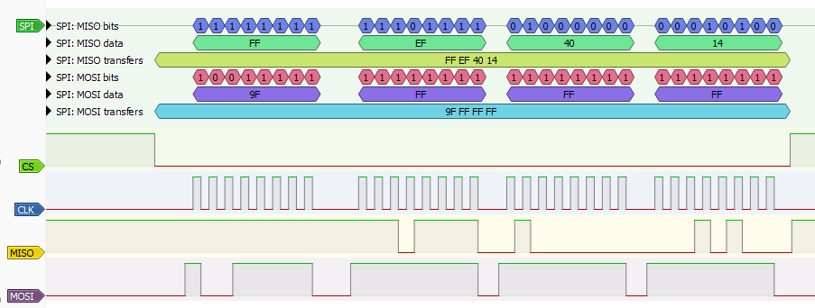
SPI (Serial Peripheral Interface) is a synchronous serial communication protocol commonly used for short-distance communication between a master device and one or more sub devices. SPI uses four main lines: SCLK (clock), MOSI (Master Out Sub In), MISO (Master In Sub Out), and CS (Chip Select).
Communication Sequence
- CS (Chip Select): Communication begins when the master pulls the CS line low, selecting the sub device.
- Master Transmission: The master sends one or more bytes over MOSI. In this example, the master writes
0x9F. - Data Response: After receiving data, the sub device can respond by sending data back over MISO. In this sequence, the sub device responds with
0xEF,0x40, and0x14. - CS High: Communication ends when the master releases the CS line (sets it high).
Data Flow Example
- CS goes low to select the device.
- Master writes
0x9F(command) on MOSI. - Sub device responds with
0xEF,0x40,0x41on MISO, one bit per clock cycle. - CS goes high to end the transaction.
Notes
- SPI is full-duplex: data can be sent and received simultaneously.
- There is no addressing on the bus; each device is selected individually using its CS line.
- The master controls the clock and initiates all communication.
Bus Pirate SPI syntax
SPI> [0x9F r:3]

CS Enabled
TX: 0x9F
RX: 0xEF 0x40 0x14
CS Disabled
SPI>
[0x9f r:3] is the Bus Pirate syntax for the SPI example above.
[- CS low (active).0x9f- Write the command0x9Fon MOSI.r:3- Read 3 bytes from MISO, which are0xEF,0x40, and0x14.]- CS high (inactive).
Connections
| Bus Pirate | Direction | Circuit | Description |
|---|---|---|---|
| MOSI | → | MOSI | Master Out Sub In |
| MISO | ← | MISO | Master In Sub Out |
| CS | → | CS | Chip Select |
| CLK | → | CLK | Clock signal |
| GND | ⏚ | GND | Signal Ground |
Configuration options
HiZ> m spi

Mode: SPI
SPI speed
 1 to 62500kHz
 x. Exit
kHz (100kHz*) >
Data bits
 4 to 8 bits
 x. Exit
Bits (8*) >
Clock polarity
 1. Idle LOW*
 2. Idle HIGH
 x. Exit
Polarity (1) >
Clock phase
 1. LEADING edge*
 2. TRAILING edge
 x. Exit
Phase (1) >
Chip select
 1. Active HIGH (CS)
 2. Active LOW (/CS)*
 x. Exit
CS (2) >
Actual speed: 99kHz
SPI>
Bus commands
| Command | Description |
|---|---|
| [ | Chip select (CS) active |
| { | Chip Select (CS) active, show the SPI read byte while writing (full duplex/write with read mode) |
| ] or } | Chip Select (CS) disable |
| r | Read one byte by sending dummy byte (0xff). (r:1…255 for bulk reads) |
| 0b | Write this binary value. Format is 0b00000000 for a byte, but partial bytes are also fine: 0b1001. |
| 0x | Write this HEX value. Format is 0x01. Partial bytes are fine: 0xA. A-F can be lower-case or capital letters. |
| 0-255 | Write this decimal value. Any number not preceded by 0x or 0b is interpreted as a decimal value. |
space | Value delimiter. Use a space to separate numbers. No delimiter is required between non-number values: {0xa6 0 0 16 5 0b111 0xaF rrrr}. |
Other Commands
Global commands are available everywhere, while mode commands are specific to the currently selected mode. Type help to see all commands in every mode, or help mode for the currently available mode commands.
Most Bus Pirate commands have extended help. Add the -h flag to any command to see the latest available options and usage examples.
flash Read/Write/Erase common flash chips
The
flash command can read, write, and erase common SPI flash memory chips directly in the Bus Pirate terminal. The Serial Flash Universal Driver at the heart of the flash command attempts to identify the flash chip and select the appropriate settings. Most modern flash chips contain SFDP tables that describe the chip capabilities. If a chip doesn’t have SFDP tables, the driver has a database of common chips on which to fall back.See Indentifying SPI Flash Chips for more information on chip markings, power requirements, and other details.
SPI> flash -h
usage:
flash [init|probe|erase|write|read|verify|test]
	[-f <file>] [-e(rase)] [-v(verify)] [-h(elp)]
Initialize and probe: flash probe
Erase and program, with verify: flash write -f example.bin -e -v
Read to file: flash read -f example.bin
Verify with file: flash verify -f example.bin
Test chip (full erase/write/verify): flash test
Force dump: flash read -o -b <bytes> -f <file>

read, write and erase flash chips using SFDP info if available
init	Reset and initialize flash chip. Default if no options given. flash
probe	Probe flash chip for ID and SFDP info. flash probe
erase	Erase flash chip. flash erase [-v(erify)]
write	Write file to flash chip. flash write -f <file> [-e(rase)] [-v(erify)]
read	Read flash chip to file. flash read -f <file>
verify	Verify flash chip against file. flash verify -f <file>
test	Erase and write full chip with dummy data, verify. flash test
-f	File flag. File to write, read or verify. flash verify -f <file>
-e	Erase flag. Add erase before write. flash write -f <file> -e
-v	Verify flag. Add verify after write or erase. flash write -f <file> -v

SPI>
Flash probe
SPI> flash probe
Probing:
		Device ID	Manuf ID	Type ID		Capacity ID
RESID (0xAB)	0x13
REMSID (0x90)	0x13		0xef
RDID (0x9F)			0xef		0x40		0x14

Initializing SPI flash...
Flash device manufacturer ID 0xEF, type ID 0x40, capacity ID 0x14
SFDP V1.5, 0 parameter headers
		Type		Ver.	Length	Address
Table 0		JEDEC (0x00)	1.5	64B	0x000080
JEDEC basic flash parameter table info:
MSB-LSB  3    2    1    0
[0001] 0xFF 0xF1 0x20 0xE5
...
[0009] 0x00 0x00 0xD8 0x10
4 KB Erase is supported throughout the device (instruction 0x20)
Write granularity is 64 bytes or larger
Flash status register is non-volatile
3-Byte only addressing
Capacity is 1048576 Bytes
Flash device supports 4KB block erase (instruction 0x20)
Flash device supports 32KB block erase (instruction 0x52)
Flash device supports 64KB block erase (instruction 0xD8)
Found a Winbond  flash chip (1048576 bytes)
Flash device reset success
flash probe searches the flash chip for any identifying information. The flash command tries three common methods to identify a flash chip (RESID, REMSID, RDID), then attempts to read the SFDP tables.
Use flash -h to see the latest options and features.
Dump a flash chip
SPI> flash dump -s 0x10 -b 32
          00 01 02 03 04 05 06 07 08 09 0A 0B 0C 0D 0E 0F  0123456789ABCDEF
----------------------------------------------------------|----------------|
00000010: 75 61 67 65 22 3A 20 30 2C 0A 22 74 65 72 6D 69 |uage": 0,."termi|
00000020: 6E 61 6C 5F 61 6E 73 69 5F 63 6F 6C 6F 72 22 3A |nal_ansi_color":|
Dump the contents of a flash chip to the terminal with the flash dump command.
-s <start address>- Optional: specify the dump start address-b <bytes>- Optional: specify the number of bytes to dump
One screen of data is displayed at a time. Press space to continue to the next screen, or ‘x’ to exit.
Disable paging with the -c flag to display all data in one go. Use the -q flag to disable the address and ASCII columns, which is useful for copying HEX values to a HEX editor.
Read a flash chip
SPI> flash read -f example.bin
Reading 1048576 bytes from flash to example.bin
[-------C o o o o o]
Read the contents of a flash chip to a file with the flash read command. The file name is specified with the -f flag.
By default the flash command will attempt to detect the flash chip and use the optimal read command. If detection fails, you can use the -o flag to override chip detection. This uses the common 0x03 read command. Specify the number of bytes to read with the -b flag.
Write a flash chip
SPI> flash write -f example.bin -e -v
Erasing 1048576 bytes
[-----------------C]
Writing 1048576 bytes from example.bin to flash
[-----------------C]
Verifying 1048576 bytes from example.bin to flash
[-------c o o o o]
Write a file to a flash chip with the flash write command. The file name is specified with the -f flag. Use the -e flag to erase the chip before writing, and the -v flag to verify the write.
Confirmation is required before erasing or writing to a flash chip. Use the -y flag to skip confirmation, but be careful with this option as it can lead to data loss if used incorrectly.
Verify a flash chip
SPI> flash verify -f example.bin
Verifying 1048576 bytes from example.bin to flash
[-------c o o o o]
Verify the contents of a flash chip against a file with the flash verify command. The file name is specified with the -f flag.
Test a flash chip
SPI> flash test
Erasing 1048576 bytes
[-----------------C]
Writing 1048576 bytes to flash
[-----------------C]
Verifying 1048576 bytes
[-------c o o o o]
The flash test command erases the chip, writes dummy data, and verifies the write. This is a way to test a chip.
Confirmation is required before erasing or writing to a flash chip. Use the -y flag to skip confirmation, but be careful with this option as it can lead to data loss if used incorrectly.
Flash Options and flags
| Option | Description |
|---|---|
flash probe | Probe flash chip for ID and SFDP info. |
flash dump | Dump flash chip contents to terminal. Space to continue, x to exit. |
flash erase | Erase flash chip. |
flash write | Write file to flash chip. Specify file with -f flag. Use -e flag to erase before write |
flash read | Read flash chip to file. Specify file with -f flag |
flash verify | Verify flash chip against file. Specify file with -f flag |
flash test | Erase and write full chip with dummy data, verify. |
Options tell the flash command what to do.
| Flag | Description |
|---|---|
-f | File flag. File to write, read or verify. |
-e | Erase flag. Add erase before write. |
-v | Verify flag. Add verify after write or erase. |
-s <start> | Specify the start address for dump operations |
-b <bytes> | Specify the number of bytes to read for dump operations |
-q | Dump quiet mode, no address or ASCII columns. Useful for copying HEX values to a HEX editor. |
-c | Dump: disable paging, display all data in one go. |
-o | Read without chip detection. Uses common 0x03 read command. Use -b flag to specify the number of bytes to read. |
Flags pass file names and other settings.
eeprom Read, write, erase, verify, test, dump SPI EEPROMs
eeprom is a command to read, write, erase, verify, test and dump common SPI and Microwire EEPROMs.You do need to specify the device type, there is no non-destructive autodetect method for SPI EEPROMs.
SPI EEPROM list supported devices
SPI> eeprom listeeprom list- list all EEPROM devices supported by theeepromcommand
25x (Microchip), AT25x (fmr. Atmel) and M95x (STM) are all compatible SPI EEPROMs. There are slight feature differences, but they all use the same command set. If you have a STM 95x EEPROM, specify the equivalent 25X device.
93x are Microwire EEPROMs, which use a older variant of the SPI protocol. They are also compatible with the SPI eeprom command.
See Indentifying SPI EEPROM Chips and Identifying Microwire EEPROMs for more information on chip markings, power requirements, and other details.
| Device | Density | Size (bytes) | Page Size (Bytes) | Address Bytes | Block Select Bits | B.S. Offset |
|---|---|---|---|---|---|---|
| 25X010 | 1 Kbit | 128 | 8(AT)/16 | 1 | 0 | |
| 25X020 | 2 Kbit | 256 | 8(AT)/16 | 1 | 0 | |
| 25X040 | 4 Kbit | 512 | 8(AT)/16 | 1 | 1 | 3 |
| 25X080 | 8 Kbit | 1024 | 16/32(AT,STM) | 2 | 0 | |
| 25X160 | 16 Kbit | 2048 | 16/32(AT,STM) | 2 | 0 | |
| 25X320 | 32 Kbit | 4096 | 32 | 2 | 0 | |
| 25X640 | 64 Kbit | 8192 | 32 | 2 | 0 | |
| 25X128 | 128 Kbit | 16384 | 64 | 2 | 0 | |
| 25X256 | 256 Kbit | 32768 | 64 | 2 | 0 | |
| 25X512 | 512 Kbit | 65536 | 128 | 2 | 0 | |
| 25XM01, 25X1024 | 1 Mbit | 131072 | 256 | 3 | 0 | |
| 25XM02 | 2 Mbit | 262144 | 256 | 3 | 0 | |
| 25XM04 | 4 Mbit | 524288 | 256/512(STM) | 3 | 0 |
25x/95x chips have a variety of part numbers, but tend to operate in the same way. Often a manufacturer specific part number indicates a different voltage range or upgraded features. AT25, 25LC, 25AA, 25CS and M95 are all part of same basic 25x family of chips.
93x are Microwire EEPROMs, which use a older variant of the SPI protocol. They are also compatible with the SPI eeprom command.
Chip voltage requirements
| 25x/95x Family | Minimum Voltage | Maximum Voltage | |
|---|---|---|---|
| AT25 | 1.8V | 5.5V | |
| 25LC | 2.5V | 5.5V | |
| 25AA | 1.8V | 5.5V | |
| 25CS | 1.7V | 5.5V | |
| M95 | 2.5V | 5.5V |
Before using the eeprom command, you’ll need to enable a power supply with the W command.
Some chips have Write Protect and Hold pins, these should also be held high for normal operation. If you’re using a flash chip adapter plank an easy way to hold these pins high is to enable pull-up resistors with the P command.
SPI EEPROM dump to terminal
SPI> eeprom dump -d 25x020 -s 0x06 -b 32
25X020: 256 bytes,  0 block select bits, 1 byte address, 8 byte pages

Start address: 0x00000000, end address: 0x0000002F, total bytes: 48

          00 01 02 03 04 05 06 07 08 09 0A 0B 0C 0D 0E 0F
---------------------------------------------------------
00000000: 55 AA 55 AA 55 AA 55 AA 55 AA 55 AA 55 AA 55 AA |U.U.U.U.U.U.U.U.|
00000010: 55 AA 55 AA 55 AA 55 AA 55 AA 55 AA 55 AA 55 AA |U.U.U.U.U.U.U.U.|
00000020: 55 AA 55 AA 55 AA 55 AA 55 AA 55 AA 55 AA 55 AA |U.U.U.U.U.U.U.U.|

SPI>
Display the contents of an EEPROM in the terminal.
eeprom dump -d <device>- display EEPROM contentseeprom dump -d <device> -s <start>- display EEPROM contents, starting at address<start>eeprom dump -d <device> -s <start> -b <bytes>- display a specific range of bytes, starting at address<start>and reading<bytes>bytes
SPI EEPROM read to file
SPI> eeprom read -d 25x020 -f eeprom.bin -v
25X020: 256 bytes,  0 block select bits, 1 byte address, 8 byte pages

Read: Reading EEPROM to file eeprom.bin...
Progress: [###########################] 100.00%
Read complete
Read verify...
Progress: [###########################] 100.00%
Read verify complete
Success :)

SPI>
Read the contents of an EEPROM and save it to a file.
eeprom read -d <device> -f <file>- read EEPROM contents to file<file>eeprom read -d <device> -f <file> -v- read EEPROM contents to file<file>, verify the read operation
SPI EEPROM write from file
SPI> eeprom write -d 25x020 -f eeprom.bin -v
25X020: 256 bytes,  0 block select bits, 1 byte address, 8 byte pages

Write: Writing EEPROM from file eeprom.bin...
Progress: [###########################] 100.00%
Write complete
Write verify...
Progress: [###########################] 100.00%
Write verify complete
Success :)

SPI>
eeprom write -d <device> -f <file>- write EEPROM from file<file>eeprom write -d <device> -f <file> -v- write EEPROM from file<file>, verify the write operation
If the file is bigger than the EEPROM, only the first bytes of the file will be written to the EEPROM. The rest of the file will be ignored.
If the file is smaller than the EEPROM, the full file will be written to the EEPROM, and the rest of the EEPROM will be left unchanged. The eeprom command will read the target page from the EEPROM, write the new data to the page, and then write the full page back to the EEPROM. This is done to avoid writing partial pages, which some devices cannot handle.
SPI EEPROM verify against file
SPI> eeprom verify -d 25x020 -f eeprom.bin
25X020: 256 bytes,  0 block select bits, 1 byte address, 8 byte pages

Verify: Verifying EEPROM contents against file eeprom.bin...
Progress: [###########################] 100.00%
Verify complete

SPI>
eeprom verify -d <device> -f <file>- verify EEPROM contents against file<file>
If the file is bigger than the EEPROM, only the first bytes of the file will be verified against the EEPROM. The rest of the file will be ignored.
If the file is smaller than the EEPROM, the full file will be verified against the EEPROM, and the rest of the EEPROM will be ignored.
SPI EEPROM erase
SPI> eeprom erase -d 25x020 -v
25X020: 256 bytes,  0 block select bits, 1 byte address, 8 byte pages

Erase: Writing 0xFF to all bytes...
Progress: [###########################] 100.00%
Erase complete
Erase verify...
Progress: [###########################] 100.00%
Erase verify complete
Success :)

SPI>
Erase the contents of an EEPROM, writing 0xFF to all bytes.
eeprom erase -d <device>- erase EEPROM contentseeprom erase -d <device> -v- erase EEPROM contents, verify the erase operation
SPI EEPROM test
SPI> eeprom test -d 25x020
25X020: 256 bytes,  0 block select bits, 1 byte address, 8 byte pages

Erase: Writing 0xFF to all bytes...
Progress: [###########################] 100.00%
Erase complete
Erase verify...
Progress: [###########################] 100.00%
Erase verify complete

Test: Writing alternating patterns
Writing 0xAA 0x55...
Progress: [###########################] 100.00%
Write complete
Write verify...
Progress: [###########################] 100.00%
Write verify complete
Writing 0x55 0xAA...
Progress: [###########################] 100.00%
Write complete
Write verify...
Progress: [###########################] 100.00%
Write verify complete
Success :)

SPI>
eeprom test -d <device>- test EEPROM functionality
SPI EEPROM show protection status
SPI> eeprom protect -d 25x020
25X020: 256 bytes,  0 block select bits, 1 byte address, 8 byte pages

Status Register: 0x00
Write Pin ENable (WPEN): Disabled
Block Protect Bits (BP1, BP0): 0, 0
Protection range: None

SPI>
eeprom protection -d <device>- show the protection status of the EEPROM
BP1, BP0, and WPEN bits
| 7 | 6 | 5 | 4 | 3 | 2 | 1 | 0 |
|---|---|---|---|---|---|---|---|
| WPEN | X | X | X | BP1 | BP0 | WEL | WIP |
Many SPI EEPROMS have some sort of write protection configured through the status register. 25X EEPROMs generally have two block protection bits (BP1, BP0) that disable writes to a memory range. The write protection can be reversed by clearing the protection bits.
| BP1 | BP0 | Protected Range |
|---|---|---|
| 0 | 0 | No protection |
| 0 | 1 | Upper 1/4 |
| 1 | 0 | Upper 1/2 |
| 1 | 1 | All |
BP1 and BP0 generally protect the upper 1/4, 1/2, or all of the EEPROM.
The WPEN bit overrides the physical write protect pin. If the WPEN bit is 0, writes are allowed even if the WP pin is held low.
Sometimes write protection is irreversible. This is pretty rare, but we’ve seen one or two chips with this non-standard feature that otherwise work like a normal 25X chip. This does not apply to the 25X chips from Atmel/Microchip, which all have reversible write protection, but you might find it on some rarer chips. Always consult the datasheet if possible, or just leave the protection bits alone.
SPI EEPROM update protection bits
SPI> eeprom protect -d 25x020 -p 0b11
25X020: 256 bytes,  0 block select bits, 1 byte address, 8 byte pages

Status Register: 0x00
Write Pin ENable (WPEN): Disabled
Block Protect Bits (BP1, BP0): 0, 0
Protection range: None

New Block protect bits (BP1, BP0): 1, 1
Updating status register (0x0C): Done :)

Status Register: 0x0C
Write Pin ENable (WPEN): Disabled
Block Protect Bits (BP1, BP0): 1, 1
Protection range: All

SPI>
eeprom protect -d <device> -b <bits>- write the block protection bits of the EEPROM.<bits>is a 2-bit value (BP1, BP0) and protects memory regions according to the table below. For example-b 0b11protects the whole EEPROM,-b 0b01protects the upper 1/4 of the EEPROM, and-b 0b00disables all protection.eeprom protect -d <device> -w <value>- write the Write Pin ENable (WPEN) bit. If the WPEN bit is 0, it overrides the physical write protect pin. For example,-w 0disables the WPEN bit, allowing writes to the EEPROM even if the pin is held high.
| BP1 | BP0 | Protected Range |
|---|---|---|
| 0 | 0 | No protection |
| 0 | 1 | Upper 1/4 |
| 1 | 0 | Upper 1/2 |
| 1 | 1 | All |
Many chips support block protection bits, fewer support the WPEN bit. To test what features a chip supports, use the -t flag to proble the write protect features.
SPI EEPROM test write protection features
SPI> eeprom protect -d 25x020 -t
25X020: 256 bytes,  0 block select bits, 1 byte address, 8 byte pages

Status Register: 0x00
Write Pin ENable (WPEN): Disabled
Block Protect Bits (BP1, BP0): 0, 0
Protection range: None

Testing support for Write Protect blocks (BP0, BP1) and Write Pin ENable (WPEN)

Disabling write protect: 0x00, OK

Testing for BP0, BP1, WPEN...wrote: 0x8C, read: 0x0C
BP0: Present
BP1: Present
WPEN: Not detected

Restoring original status register: 0x00...Done :)
Status Register: 0x00
Write Pin ENable (WPEN): Disabled
Block Protect Bits (BP1, BP0): 0, 0
Protection range: None

SPI>
25X EEPROMs frequently have block protection (BP) bits that disable writes to a memory range. Newer chips also have a Write Pin ENable (WPEN) bit that overrides the physical write protect pin. To probe the write protection features we try to enable all of them, then check which were actually enabled. The command will restore the original protection settings after the test.
eeprom protect -d <device> -t- test the write protection features of the EEPROM.
SPI EEPROM options and flags
SPI> eeprom -h
usage:
eeprom [dump|erase|write|read|verify|test|list|protect]
	[-d <device>] [-f <file>] [-v(verify)] [-s <start address>] [-b <bytes>] [-t(test)] [-p <protection blocks>] [-w <WPEN>] [-h(elp)]
List available EEPROM devices: eeprom list
Display contents: eeprom dump -d 25x020
Display 16 bytes starting at address 0x60: eeprom dump -d 25x020 -s 0x60 -b 16
Erase, verify: eeprom erase -d 25x020 -v
Write from file, verify: eeprom write -d 25x020 -f example.bin -v
Read to file, verify: eeprom read -d 25x020 -f example.bin -v
Verify against file: eeprom verify -d 25x020 -f example.bin
Test chip (full erase/write/verify): eeprom test -d 25x020
Probe Status Register block protection: eeprom protect -d 25x020
Test for chip block protection features: eeprom protect -d 25x020 -t
Disable all block protection bits (BP1, BP0): eeprom protect -d 25x020 -p 0b00
Disable Write Pin ENable (WPEN): eeprom protect -d 25x020 -w 0

read, write and erase 25XX series SPI EEPROM chips
dump	Show contents
erase	Erase chip
write	Write file to chip
read	Read chip to file
verify	Verify chip against file
test	Erase and write chip with dummy data, verify
list	List supported EEPROM devices
protect	Show chip write protect status
-d	Specify the EEPROM device
-f	File to write, read or verify
-v	Verify after read, write or erase
-s	Dump start address
-b	Bytes to dump
-t	Test for write protection features
-p	Set Block Protection bits (0b00-0b11, 0-3)
-w	Set Write Protect ENable pin off/on (0/1)
-h	Get additional help

SPI>
| Option | Description |
|---|---|
eeprom list | List all supported EEPROM devices |
eeprom dump | Dump EEPROM contents to terminal. Space to continue, x to exit. |
eeprom read | Read EEPROM contents to file |
eeprom write | Write EEPROM from file |
eeprom verify | Verify EEPROM contents against file |
eeprom erase | Erase EEPROM contents, writing 0xFF to all bytes |
eeprom test | Test EEPROM functionality, erase and write alternating patterns |
eeprom protect | Show, update, test the write protection status of the EEPROM |
Options tell the eeprom command what to do.
Always check the latest options and flags with eeprom -h to see the most up-to-date features.
| Flag | Description |
|---|---|
-d <device> | Specify the EEPROM device type, e.g. 24x02 |
-f <file> | Specify the file for read, write and verify |
-v | Verify the read or write operation |
-p <value> | Update the block protection bits, 0b00-0b11 valid |
-w <value> | Update the Write Pin ENable (WPEN) bit, 0 to disable, 1 to enable |
-t | Test the write protection features of the EEPROM |
-s <start> | Specify the start address for dump operations |
-b <bytes> | Specify the number of bytes to read for dump operations |
-q | Dump quiet mode, no address or ASCII columns. Useful for copying HEX values to a HEX editor. |
-c | Dump: disable paging, display all data in one go. |
-h | Show help for the eeprom command |
Flags pass file names and other settings.
Device demos
2-WIRE
- Bus: 2 wire bus with bidirectional data (SDA) line and a clock (SCL) line
- Connections: two data pins (SDA/SCL) and ground. An additional pin is reserved for RESET, and is controlled by the
{/}commands. - Output type: open drain/open collector
- Pull-up resistors: always required (2K - 10K ohms)
- Maximum voltage: 5volts
2-wire is a generic 8bit protocol mode with a bidirectional data line (SDA) and a clock line (SCL). 2-wire can be used to interface with SLE4442 smart cards, half-duplex SPI devices and other 2 wire busses that don’t use a full I2C implementation.
Connections
| Bus Pirate | Direction | Circuit | Description |
|---|---|---|---|
| SDA | ↔ | SDA | Serial Data |
| SCL | → | SCL | Serial Clock |
| RST | → | RST | Reset signal for some devices |
| GND | ⏚ | GND | Signal Ground |
Configuration options
HiZ> m 2wire

Mode: 2WIRE
2WIRE speed
 1kHz to 1000kHz
 x. Exit
kHz (400kHz*) >
2WIRE>
Pull-up resistors
2-Wire is an open-collector bus, it requires pull-up resistors to hold the clock and data lines high and create the data ‘1’. In 2-Wire mode, the Bus Pirate doesn’t output high, it only pulls low. Without pull-up resistors there can never be a ‘1’.
Enable the Bus Pirate onboard pull-up resistors with the P command.
2-Wire requires pull-up resistors to hold the clock and data lines high.
Without pull-up resistors there can never be a ‘1’.
Enable the Bus Pirate onboard pull-up resistors with the
Pcommand.
Bus commands
| Command | Description |
|---|---|
| [ | Issue I2C-style START condition. Some devices don’t follow the I2C standard, but still use a similar START condition. |
| ] | Issue I2C-style STOP condition. Some devices don’t follow the I2C standard, but still use a similar STOP condition. |
| { | RST/reset pin high |
| } | RST/reset pin low |
| r | Read one byte. (r:1…255 for bulk reads) |
| 0b | Write this binary value. Format is 0b00000000 for a byte, but partial bytes are also fine: 0b1001. |
| 0x | Write this HEX value. Format is 0x01. Partial bytes are fine: 0xA. A-F can be lower-case or capital letters. |
| 0-255 | Write this decimal value. Any number not preceded by 0x or 0b is interpreted as a decimal value. |
space | Value delimiter. Use a space to separate numbers. No delimiter is required between non-number values: {0xa6 0 0 16 5 0b111 0xaF rrrr}. |
| ^ | One clock tick, low to high to low transition. |
| / | Set clock pin high. |
| \ | Set clock pin low. |
| _ | Set data pin low. |
| - | Set data pin high. |
| . | Read data pin. |
2WIRE supports bitwise operations on the clock and data lines. The commands ^, /, \, _, - and . control the clock and data lines directly. This is useful for some devices that require precise timing or specific signal patterns.
Other Commands
Global commands are available everywhere, while mode commands are specific to the currently selected mode. Type help to see all commands in every mode, or help mode for the currently available mode commands.
Most Bus Pirate commands have extended help. Add the -h flag to any command to see the latest available options and usage examples.
sniff 2WIRE bus sniffer
2WIRE> sniff -h
usage:
sniff [-q]
Start the 2WIRE sniffer: sniff

Sniffs SLE4442 style 8bit I2C-like protocols (no NAK/ACK)
Based on pico-i2c-sniff by @jjsch-dev https://github.com/jjsch-dev/pico_i2c_sniffer
Max speed: 500kHz

I2C sniffer
h	Get additional help

2WIRE>
Sniff 8 bit I2C-like protocols that don’t use an ACK/NAK bit, for example the SLE4442 smart card.
sle4442 Work with SLE4442 smart cards
The
sle4442 command in the Bus Pirate’s 2-WIRE mode automates the process of reading, writing and unlocking a SLE4442 smart card.Use sle4442 -h to see the latest options and features.
SLE4442 Answer to Reset (ATR)
2WIRE> sle4442 init
--SLE44xx decoder--
ATR: 0xa2 0x13 0x10 0x91
Protocol Type: S 10
Structure Identifier: General Purpose (Structure 1)
Read: Read to end
Data Units: 256
Data Units Bits: 8
Security memory: 0x07 0x00 0x00 0x00
Remaining attempts: 3 (0x7)

2WIRE>
sle4442 and sle4442 init reset the card and decodes the Answer To Reset (ATR) response.
sle4442 init- reset the card and decode the ATR
Dump SLE4442 card memory
2WIRE> sle4442 dump
--SLE44xx decoder--
ATR: 0xa2 0x13 0x10 0x91
Protocol Type: S 10
Structure Identifier: General Purpose (Structure 1)
Read: Read to end
Data Units: 256
Data Units Bits: 8
Security memory: 0x07 0x00 0x00 0x00
Remaining attempts: 3 (0x7)
Protection memory: 0xff 0xff 0xff 0xff
Memory:
Start address: 0x00000000, end address: 0x000000FF, total bytes: 256

          00 01 02 03 04 05 06 07 08 09 0A 0B 0C 0D 0E 0F
---------------------------------------------------------
00000000: A2 13 10 91 FF FF 81 15 FF FF FF FF FF FF FF FF |................|
00000010: FF FF FF FF FF D2 76 00 00 04 00 FF FF FF FF FF |......v.........|
00000020: FF FF FF FF FF FF FF FF FF FF FF FF FF FF FF FF |................|
00000030: FF FF FF FF FF FF FF FF FF FF FF FF FF FF FF FF |................|
00000040: FF FF FF FF FF FF FF FF FF FF FF FF FF FF FF FF |................|
00000050: FF FF FF FF FF FF FF FF FF FF FF FF FF FF FF FF |................|
00000060: FF FF FF FF FF FF FF FF FF FF FF FF FF FF FF FF |................|
00000070: FF FF FF FF FF FF FF FF FF FF FF FF FF FF FF FF |................|
00000080: FF FF FF FF FF FF FF FF FF FF FF FF FF FF FF FF |................|
00000090: FF FF FF FF FF FF FF FF FF FF FF FF FF FF FF FF |................|
000000A0: FF FF FF FF FF FF FF FF FF FF FF FF FF FF FF FF |................|
000000B0: FF FF FF FF FF FF FF FF FF FF FF FF FF FF FF FF |................|
000000C0: FF FF FF FF FF FF FF FF FF FF FF FF FF FF FF FF |................|
000000D0: FF FF FF FF FF FF FF FF FF FF FF FF FF FF FF FF |................|
000000E0: FF FF FF FF FF FF FF FF FF FF FF FF FF FF FF FF |................|
000000F0: FF FF FF FF FF FF FF FF FF FF FF FF FF FF FF FF |................|


2WIRE>
sle4442 dump reads and displays the main, security and protection memory areas. The card does not need to be unlocked to read the contents. The passcode is only required to write to the card.
sle4442 dump- read and display the main, security and protection memory areassle4442 dump -s 0x06 -b 32- read and display the main memory area starting at address 0x06, reading 32 bytessle4442 dump -f <file name>- read and save the main, security and protection memory areas to a file
Unlock SLE4442 card with passcode
2WIRE> sle4442 unlock -p 0xffffff
--SLE44xx decoder--
ATR: 0xa2 0x13 0x10 0x91
Protocol Type: S 10
Structure Identifier: General Purpose (Structure 1)
Read: Read to end
Data Units: 256
Data Units Bits: 8
Security memory: 0x07 0x00 0x00 0x00
Remaining attempts: 3 (0x7)
Unlocking with PSC: 0xFFFFFF
Using free security bit: 0x03
Card unlocked, security bits reset
Security memory: 0x07 0xff 0xff 0xff
Remaining attempts: 3 (0x7)

2WIRE>
sle4442 unlock unlocks the card using the Programmable Security Code (PSC). Use the -p flag to specify the PSC.
sle4442 unlock -p <psc>- unlock the card with the current PSC
New cards usually have a default PSC of 0xffffff.
Write data to SLE4442 card
2WIRE> sle4442 write -a 0xff -v 0x88
--SLE44xx decoder--
ATR: 0xa2 0x13 0x10 0x91
Protocol Type: S 10
Structure Identifier: General Purpose (Structure 1)
Read: Read to end
Data Units: 256
Data Units Bits: 8
Security memory: 0x07 0xff 0xff 0xff
Remaining attempts: 3 (0x7)
Writing 0x88 to 0xff

2WIRE>
sle4442 write writes a single byte of data to the card. Specify the address with the -a flag and the data value with the -v flag.
sle4442 write -a <address> -v <value>- write a byte of data to the card
The card must be unlocked before writing data.
Change SLE4442 passcode/PSC
2WIRE> sle4442 psc -p 0xffffff -n 0x123456
--SLE44xx decoder--
ATR: 0xa2 0x13 0x10 0x91
Protocol Type: S 10
Structure Identifier: General Purpose (Structure 1)
Read: Read to end
Data Units: 256
Data Units Bits: 8
Security memory: 0x07 0xff 0xff 0xff
Remaining attempts: 3 (0x7)
Unlocking with PSC: 0xFFFFFF
Using free security bit: 0x03
Card unlocked, security bits reset
Security memory: 0x07 0xff 0xff 0xff
Remaining attempts: 3 (0x7)
Updating with PSC: 0x123456
PSC updated to: 0x123456
Security memory: 0x07 0x12 0x34 0x56
Remaining attempts: 3 (0x7)

2WIRE>
sle4442 psc changes the Programmable Security Code (PSC). Use the -p flag to specify the current PSC and the -n flag to specify the new PSC.
sle4442 psc -p <current_psc> -n <new_psc>- change the PSC
Write protection memory
Write the protection bits in the SLE4442 card with the sle4442 protect command. Use the -v flag to specify the protection bits. The protection bits are a 32-bit value where each bit corresponds to a specific memory area.
sle4442 protect -v 0xffffffffsets the write protection bits in the SLE4442 card. Use the-vflag to specify the protection bits.
Options and flags
2WIRE> sle4442 -h
usage:
sle4442 [init|dump|unlock|write|erase|psc]
	[-a <address>] [-v <value>] [-p <current psc>] [-n <new psc>] [-f <dump file>] [-h(elp)]
Initialize and probe: sle4442 init
Dump contents: sle4442 dump
Unlock card: sle4442 unlock -p 0xffffff
Write a value: sle4442 write -a 0xff -v 0x55
Erase memory: sle4442 erase
Update PSC: sle4442 psc -p 0xffffff -n 0x000000
Dump contents to file: sle4442 dump -f dump.bin
Dump format: DATA[0:255],SECMEM[256:259],PRTMEM[260:263]

SLE4442 smart card interface
init	Initialize card with ISO7816-3 ATR. Default action
dump	Display main, security and protect memory
unlock	Unlock card with Programmable Security Code (PSC)
write	Write data to card (requires unlock)
erase	Erase data from range 0x32-0x255 (requires unlock)
psc	Change Programmable Security Code (PSC)
-a	Write address flag
-v	Write value flag
-p	Current Programmable Security Code (PSC) flag
-n	New Programmable Security Code (PSC) flag
-f	Dump file name flag

2WIRE>
Use sle4442 -h to see the latest options and features.
| Option | Description |
|---|---|
| sle4442 init | Initialize and probe the card Answer To Reset |
| sle4442 dump | Display main, security and protect memory, optional save to file |
| sle4442 unlock | Unlock card with Programmable Security Code (PSC) |
| sle4442 write | Write data to card (requires unlock) |
| sle4442 erase | Erase data from range 0x32-0x255 (requires unlock) |
| sle4442 psc | Change Programmable Security Code (PSC) |
| sle4442 protect | Set write protection bits in the card |
Options tell the SLE4442 command what to do.
| Flag | Description |
|---|---|
| -a | Write address flag |
| -v | Write value flag |
| -p | Current Programmable Security Code (PSC) flag |
| -n | New Programmable Security Code (PSC) flag |
| -f | File flag, specify a file to save the memory dump |
| -s | Start address for memory dump |
| -b | Number of bytes in memory dump |
| -q | Memory dump quiet mode, no address or ASCII columns. Useful for copying HEX values to a HEX editor. |
Flags pass file names and other settings to the command.
Device demos
3-WIRE
- Bus: SPI-like bus with granular control of the clock and data lines
- Connections: four data pins (MOSI/MISO/CLOCK/CHIP_SELECT) and ground
- Output type: push-pull (1.65-5volts)
- Maximum voltage: 5volts
3WIRE is like SPI with extra commmands to control the clock and data lines individually.
Connections
| Bus Pirate | Direction | Circuit | Description |
|---|---|---|---|
| MOSI | → | MOSI | Master Out Sub In |
| MISO | ← | MISO | Master In Sub Out |
| CS | → | CS | Chip Select |
| CLK | → | CLK | Clock signal |
| GND | ⏚ | GND | Signal Ground |
Configuration options
HiZ> m 3wire

Mode: 3WIRE
Speed
 1 to 3900kHz
 x. Exit
kHz (100kHz*) >
Chip select
 1. Active HIGH (CS)
 2. Active LOW (/CS)*
 x. Exit
CS (2) >
3WIRE>
Bus commands
| Command | Description |
|---|---|
| [ | Chip select (CS) active |
| { | Chip Select (CS) active, show the SPI read byte while writing |
| ] or } | Chip Select (CS) disable |
| r | Read one byte. (r:1…255 for bulk reads) |
| 0b | Write this binary value. Format is 0b00000000 for a byte, but partial bytes are also fine: 0b1001. |
| 0x | Write this HEX value. Format is 0x01. Partial bytes are fine: 0xA. A-F can be lower-case or capital letters. |
| 0-255 | Write this decimal value. Any number not preceded by 0x or 0b is interpreted as a decimal value. |
space | Value delimiter. Use a space to separate numbers. No delimiter is required between non-number values: {0xa6 0 0 16 5 0b111 0xaF rrrr}. |
| ^ | One clock tick, low to high to low transition. |
| / | Set clock pin high. |
| \ | Set clock pin low. |
| _ | Set MOSI pin low. |
| - | Set MOSI pin high. |
| . | Read MISO pin. |
3WIRE supports bitwise operations on the clock and data lines. The commands ^, /, \, _, - and . control the clock and data lines directly. This is useful for some devices that require precise timing or specific signal patterns.
Other Commands
Global commands are available everywhere, while mode commands are specific to the currently selected mode. Type help to see all commands in every mode, or help mode for the currently available mode commands.
Most Bus Pirate commands have extended help. Add the -h flag to any command to see the latest available options and usage examples.
DIO
- Bus: DIO (digital input/output)
- Connections: all IOs available for use
- Output type: tristate (push-pull, high impedance) (1.65-5volts)
- Maximum voltage: 5volts
DIO is a mode with no specific protocol. All the Bus Pirate pins are free for use as input/ouputs, frequency generators, frequency measurement, etc.
DIO> > 0xff

TX: 0xFF
DIO> > 0x00

TX: 0x00
DIO> > 0b10101010

TX: 0b10101010
DIO> > 0b01010101

TX: 0b01010101
Bus commands can be used to control all the unused IO pins at once, or use r to read the state of all pins.
>0x00- set all pins low>0xff- set all pins high>0b10101010- set every other pin high/low>0b01010101- set every other pin low/high>r- read the state of all pins>@.0- make pin 0 an input (used in bus command context)@ 0- make pin 0 an input (note no>is used)
Return a pin to input with the @ auxiliary pin read command.
Pins with active frequency generation or measurement are not changed.
Don’t forget to start bus command with the > bus command character.
LED - WS2812/SK6812/‘NeoPixel’
- Bus: WS2812/SK6812/‘NeoPixel’ one wire
- Connections: one data pin (SDO), and ground
- Output type: 1.65-5volts
- Maximum voltage: 5volts
WS2812/SK6812 are common RGB LEDs with a one wire interface.
LEDs are power hungry, up to 60mA each at full brightness. The programmable power supply is rated for 300mA maximum. The LEDs will need an external power supply when driving more than a few in a strip.
Connections
| Bus Pirate | Direction | Circuit | Description |
|---|---|---|---|
| SDO | → | DIN | Serial Data Out |
| GND | ⏚ | GND | Signal Ground |
Configuration options
HiZ> m led

Mode: LED
LED type
 1. WS2812/SK6812/'NeoPixel' (single wire interface)*
 2. APA102/SK9822 (clock and data interface)
 3. Onboard LEDs (18 SK6812s)
 x. Exit
Type (1) >
LED-(WS2812)>
Bus commands
| Command | Description |
|---|---|
| [ or { | Reset (low for >280us) |
| ] or } | – |
| 0b | Write this binary value. Format is 0b00000000 for a byte, but partial bytes are also fine: 0b1001. |
| 0x | Write this HEX value. Format is 0x01. Partial bytes are fine: 0xA. A-F can be lower-case or capital letters. |
| 0-255 | Write this decimal value. Any number not preceded by 0x or 0b is interpreted as a decimal value. |
space | Value delimiter. Use a space to separate numbers. No delimiter is required between non-number values: {0xa6 0 0 16 5 0b111 0xaF rrrr}. |
Other Commands
Global commands are available everywhere, while mode commands are specific to the currently selected mode. Type help to see all commands in every mode, or help mode for the currently available mode commands.
Most Bus Pirate commands have extended help. Add the -h flag to any command to see the latest available options and usage examples.
Device demos
LED - APA102/SK9822
- Bus: APA102/SK9822 two wire
- Connections: two data pins (SDO, SCL), and ground
- Output type: 1.65-5volts
- Maximum voltage: 5volts
APA102/SK9822 are common RGB LEDs with a two wire interface.
LEDs are power hungry, up to 60mA each at full brightness. The programmable power supply is rated for 300mA maximum. The LEDs will need an external power supply when driving more than a few in a strip.
Connections
| Bus Pirate | Direction | Circuit | Description |
|---|---|---|---|
| SDO | → | SDI | Serial Data Out |
| SCL | → | CKI | Serial Clock |
| GND | ⏚ | GND | Signal Ground |
Configuration options
HiZ> m led

Mode: LED
LED type
 1. WS2812/SK6812/'NeoPixel' (single wire interface)*
 2. APA102/SK9822 (clock and data interface)
 3. Onboard LEDs (18 SK6812s)
 x. Exit
Type (1) >
LED-(WS2812)>
Bus commands
| Command | Description |
|---|---|
| [ or { | Start Frame (0x00000000) |
| ] or } | End Frame (0xffffffff) |
| 0b | Write this binary value. Format is 0b00000000 for a byte, but partial bytes are also fine: 0b1001. |
| 0x | Write this HEX value. Format is 0x01. Partial bytes are fine: 0xA. A-F can be lower-case or capital letters. |
| 0-255 | Write this decimal value. Any number not preceded by 0x or 0b is interpreted as a decimal value. |
space | Value delimiter. Use a space to separate numbers. No delimiter is required between non-number values: {0xa6 0 0 16 5 0b111 0xaF rrrr}. |
Other Commands
Global commands are available everywhere, while mode commands are specific to the currently selected mode. Type help to see all commands in every mode, or help mode for the currently available mode commands.
Most Bus Pirate commands have extended help. Add the -h flag to any command to see the latest available options and usage examples.
Device demos
INFRARED - RAW
- Bus: Infrared (IR) signals (raw)
- Connections: one transmit pin, one receive pin and ground
- Output type: open drain input, push-pull output (1.65-5volts)
- Maximum voltage: 5volts
Infrared is a mode for sending and receiving infrared signals. The Bus Pirate can send and receive RC5 and NEC protocols, and raw IR signals. Compatible with the IR Toy v3 plank.
Connections
| Bus Pirate | Direction | Circuit | Description |
|---|---|---|---|
| LERN (IO1) | ← | LEARNER | 20-60kHz IR learner receiver |
| BARR (IO3) | ← | 38K BARRIER | 38kHz IR barrier receiver |
| IRTX (IO4) | → | TRANSMIT | IR transmitter LED |
| 38K (IO5) | ← | 38K DEMODULATOR | 36-40kHz IR demodulator |
| 56K (IO7) | ← | 56K DEMODULATOR | 56kHz IR demodulator |
Configuration options
HiZ> m infrared

Mode: INFRARED
Protocol
 1. RAW (aIR format)*
 2. NEC
 3. RC5
 x. Exit
Protocol (1) >
TX modulation
 20kHz to 60kHz
 x. Exit
kHz (38kHz*) >
RX sensor
 1. 38kHz barrier
 2. 36-40kHz demodulator*
 3. 56kHz demodulator
 x. Exit
RX sensor (2) >
INFRARED-(RAW)>
Bus commands
Other Commands
Global commands are available everywhere, while mode commands are specific to the currently selected mode. Type help to see all commands in every mode, or help mode for the currently available mode commands.
Most Bus Pirate commands have extended help. Add the -h flag to any command to see the latest available options and usage examples.
tvbgone
TV-B-Gone, turn off many brands of TV
irtx
Transmit IR signals (aIR format)
irrx
Receive, record, retransmit IR signals (aIR format)
Device demos
INFRARED - NEC
- Bus: NEC Infrared (IR) remote control protocol
- Connections: one transmit pin, one receive pin and ground
- Output type: open drain input, push-pull ouput (1.65-5volts)
- Maximum voltage: 5volts
Infrared is a mode for sending and receiving infrared signals. The Bus Pirate can send and receive RC5 and NEC protocols, and raw IR signals. Compatible with the IR Toy v3 plank.
Connections
| Bus Pirate | Direction | Circuit | Description |
|---|---|---|---|
| BARR (IO3) | ← | 38K BARRIER | 38kHz IR barrier receiver |
| IRTX (IO4) | → | TRANSMIT | IR transmitter LED |
| 38K (IO5) | ← | 38K DEMODULATOR | 36-40kHz IR demodulator |
| 56K (IO7) | ← | 56K DEMODULATOR | 56kHz IR demodulator |
Configuration options
HiZ> m infrared

Mode: INFRARED
Protocol
 1. RAW (aIR format)*
 2. NEC
 3. RC5
 x. Exit
Protocol (1) >
TX modulation
 20kHz to 60kHz
 x. Exit
kHz (38kHz*) >
RX sensor
 1. 38kHz barrier
 2. 36-40kHz demodulator*
 3. 56kHz demodulator
 x. Exit
RX sensor (2) >
INFRARED-(RAW)>
Bus commands
Other Commands
Global commands are available everywhere, while mode commands are specific to the currently selected mode. Type help to see all commands in every mode, or help mode for the currently available mode commands.
Most Bus Pirate commands have extended help. Add the -h flag to any command to see the latest available options and usage examples.
Device demos
INFRARED - RC5
- Bus: RC5 Infrared (IR) remote control protocol
- Connections: one transmit pin, one receive pin and ground
- Output type: open drain input, push-pull ouput (1.65-5volts)
- Maximum voltage: 5volts
Infrared is a mode for sending and receiving infrared signals. The Bus Pirate can send and receive RC5 and NEC protocols, and raw IR signals. Compatible with the IR Toy v3 plank.
Connections
| Bus Pirate | Direction | Circuit | Description |
|---|---|---|---|
| BARR (IO3) | ← | 38K BARRIER | 38kHz IR barrier receiver |
| IRTX (IO4) | → | TRANSMIT | IR transmitter LED |
| 38K (IO5) | ← | 38K DEMODULATOR | 36-40kHz IR demodulator |
| 56K (IO7) | ← | 56K DEMODULATOR | 56kHz IR demodulator |
Configuration options
HiZ> m infrared

Mode: INFRARED
Protocol
 1. RAW (aIR format)*
 2. NEC
 3. RC5
 x. Exit
Protocol (1) >
TX modulation
 20kHz to 60kHz
 x. Exit
kHz (38kHz*) >
RX sensor
 1. 38kHz barrier
 2. 36-40kHz demodulator*
 3. 56kHz demodulator
 x. Exit
RX sensor (2) >
INFRARED-(RAW)>
Bus commands
Other Commands
Global commands are available everywhere, while mode commands are specific to the currently selected mode. Type help to see all commands in every mode, or help mode for the currently available mode commands.
Most Bus Pirate commands have extended help. Add the -h flag to any command to see the latest available options and usage examples.
Device demos
JTAG
- Bus: JTAG
- Connections: varries
- Output type: push-pull (1.65-5volts)
- Maximum voltage: 5volts
JTAG mode is NOT for working directly with JTAG devices (yet!). JTAG mode hosts blueTag, an open source JTAG and SWD pin finder.
bluetag JTAG & SWD pinout finder
blueTag is an open source JTAG and SWD pin finder integrated into the Bus Pirate firmware. It can identify the JTAG/SWD pins on a target device by sending a series of test signals and analyzing the responses.
Connections
- Connect the Bus Pirate IO pins to the suspected JTAG/SWD pins on the target device.
- Start with IO0 and work your way up to IO7.
- If possible, look for ground pours and power pins on the JTAG or SWD port and avoid connecting IO pins to them.
- Connect the Bus Pirate ground pin to the target device ground.
- Power the device.
Measure the target device supply/pin voltage. The Bus Pirate IO pins should set to match with the W power supply command.
If the target has an obvious voltage out pin, then you can power the Bus Pirate IO pins from that. Attach the Bus Pirate VOUT pin to the target voltage out pin and skip the W power supply command setup step.
Search for JTAG pins
JTAG> bluetag jtag -c 8
Number of channels set to: 8

     Progress: [##########################] 100.00%

     [  Pinout  ]  TDI=IO0 TDO=IO3 TCK=IO4 TMS=IO2 TRST=N/A

     [ Device 0 ]  0x59602093 (mfg: 'Xilinx', part: 0x9602, ver: 0x5)

JTAG>
bluetag jtag -c <channels>- search for JTAG pins on the target device. The-cflag specifies the number of channels to search, starting from IO0.
This chip is identified as a Xilinx device with the pinout: TDI=IO0 TDO=IO3 TCK=IO4 TMS=IO2 TRST=N/A.
If the scan fails, you can try again with the -d flag to disable pin pulsing. This may help find stubborn JTAG pins.
Search for SWD pins
JTAG> bluetag swd -c 8
Number of channels set to: 8

     Progress: [##########################] 100.00%

     [  Pinout  ]  SWDIO=IO5 SWCLK=IO6

     [ Device 0 ]  0x0BC12477 (mfg: 'ARM Ltd', part: 0xbc12, ver: 0x0)

JTAG>
bluetag swd -c <channels>- search for SWD pins on the target device. The-cflag specifies the number of channels to search, starting from IO0.
This chip is identified as an ARM device with the pinout: SWDIO=IO5 SWCLK=IO6.
The Bus Pirate can find its own SWD pins. Connect IO0-IO2 to the three debug pins on the bottom of the Bus Pirate and then run bluetag swd -c 3.
bluetag Options
JTAG> bluetag -h
usage:
bluetag [jtag|swd] [-c <channels>] [-v(ersion)] [-d(isable pulsing)]
blueTag interactive interface: bluetag
JTAG scan, 6 channels: bluetag jtag -c 6
SWD scan, 4 channels: bluetag swd -c 4
Show version: bluetag -v
Disable JTAG pin pulsing: bluetag jtag -c 6 -d

blueTag by @Aodrulez https://github.com/Aodrulez/blueTag

blueTAG options
jtag	Scan for JTAG pins
swd	Scan for SWD pins

Flags
-c	Number of channels to scan (starting from IO0)
-v	Show version
-d	Disable pin pulsing (JTAG mode)

JTAG>
| Option | Description |
|---|---|
-c <channels> | Number of channels to search, starting from IO0. |
-v | Show blueTag version. |
-d | Disable pin pulsing, may help if normal search fails. |
-h | Show help message. |